example_unstructured_grid_config.zip
What | Required | Description | schema location |
|---|---|---|---|
Grids.xml | no | Grid definitions, either regular or irregular |
DELFT-FEWS is a location oriented system. All time series data must be referenced to a (geographic) location. Scalar time series need no additional information. For grid time series data, each point in the grid must be referenced to a location in a grid structure.
Grids may be regular or irregular. In regular grids each cell has the same width, height and area within the coordinate system it is specified in.
In irregular grids the grid has a fixed number of rows and columns, but the cell height and width is not equal in each row and column. For these grids additional information is required on the location of each individual cell in the grid to allow display in the grids display as well as for use in the spatial interpolation routine.
For regular grids it is sometimes not required to add the location to the grids.xml when you only want to import/export the grid. Most grid transformations will not work when the output location is missing in the grids.xml. Regular grids that need a custom projection (projectionFile, polarStereoGraphic, geostationarySatelliteView, transverseMercator, mercator, albersEqualArea, azimuthalEquidistant, lambertAzimuthalEqualArea, rotatedCartesian, lambertConformalConic, rotatedSouthPole, rotatedNorthPole, rotatedCartesian, azimuthalEquidistant) should ALWAYS be listed in the grids.xml. The grid geometry should be available in the imported file (netcdf/grib).
When available on the file system, the name of the XML file is for example:
Grids 1.00 default.xml
Grids Fixed file name for the Grids configuration
1.00 Version number
default Flag to indicate the version is the default configuration (otherwise omitted).

Figure 28 Elements of the grids configuration
regular
Definition of a regular grid. One or more regular grids may be defined.
Attributes;
- locationId; location Id of the grid. This locationId must be included in the locations definition.
irregular
Definition of a irregular grid. One or more irregular grids may be defined.
Attributes;
- locationId; location Id of the grid. This locationId must be included in the locations definition.
Regular grids
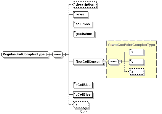
Figure 29 Elements of the Regular Grid in the Grids configuration
description
Optional description of the grid. Used only for reference purposes
rows, columns
Number of rows and columns in the grid
geoDatum
Coordinate system the grid is defined in. This may be a different coordinate system to that used in the main map display. The coordinate system may also differ per grid, as a grid may be regular in one coordinate system, but may be irregular in another. Defining the grid in the regular coordinate system is easier.
firstCellCenter
Coordinates of the center of the first grid cell. The convention in DELFT-FEWS is that this is the center point of the top left cell in the grid (Upper-Left).
firstCellCenter: x
Geographic coordinate of the first cell center point (Easting)
firstCellCenter: y
Geographic coordinate of the first cell center point (Northing)
firstCellCenter: z
Optional elevation of the first cell center point (Easting). If only this elevation is defined , then all cells in the grid are assumed to have the same elevation.
xCellSize / columnWidth
Cell width of each column in the grid. The cell width is given in the unit of the coordinate system referred to in the geoDatum. Generally this is metres, but in WGS 1984 this is decimal degrees.
The xCellSize-element is used when all cells are equal in width. Please use the columnWidth-element to define cells with variable columnWidth.
yCellSize / rowHeigt
Cell height of each row in the grid. The cell height is given in the unit of the coordinate system referred to in the geoDatum. Generally this is metres, but in WGS 1984 this is decimal degrees.
The yCellSize-element is used when all cells are equal in height. Please use the rowHeight-element to define cells with variable height.
z / zBottom / zTop
Optional definition of the elevation of each point in the grid. This definition is only necessary where a datum is required in for example 3-dimensional interpolation. This may be applied in for example interpolating temperature grids in high mountain areas. Alternative uses are the display of elevation in a cross section of the Spatial Display. The bottom/top layer is only displayed if the parameter unit is meters and if the corresponding displayOptions are configured in the TimeSeriesDisplayConfig file and if the layer contains non-NaN values. The useDatum property is not used here.
Use 'z' for the average elevation, and zBottom and zTop in case a model layer needs to be defined
zMapLayerName / zBottomMapLayerName / zTopMapLayerName
Optional definition of the elevation by reference to an ASC or BIL file stored in the MapLayerFiles-directory. This definition is only necessary where a datum is required in for example 3-dimensional interpolation. This may be applied in for example interpolating temperature grids in high mountain areas. Alternative uses are the display of elevation in a cross section of the Spatial Display. The bottom/top layer is only displayed if the parameter unit is meters and if the corresponding displayOptions are configured in the TimeSeriesDisplayConfig file and if the layer contains non-NaN values. The useDatum property is not used here.
Use 'zMapLayerNAme' for the average elevation, and zBottomMapLayerName and zTopMapLayerName in case a model layer needs to be defined.
Irregular grids
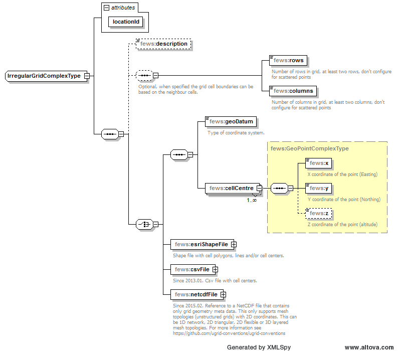
Figure 30 Elements of the irregular grid in the Grids configuration
description
Optional description of the grid. Used only for reference purposes
rows, columns
Optional, when specified the grid cell boundaries can be based on the neighbor cells. Number of rows and columns in grid, at least two rows and two columns. Don't configure this for scattered point grids.
geoDatum
Coordinate system the grid is defined in. This may be a different coordinate system to that used in the main map display. The coordinate system may also differ per grid. A grid may be regular in one coordinate system, but may be irregular in another. Defining the grid in the regular coordinate system is generally easier.
You can also use the EPSG codes
cellCentre
Definition of the cell centre points of all cells in the irregular grid. The number of cellCentre points defined must be the same as the number of cells in the grid (rows x columns).
cellCentre: x, cellCentre: y
Geographic coordinates of the cell centre point (x: Easting, y: Northing).
cellCentre: z
Elevation of the cell centre point.
esriShapeFile
Shape file with cell polygons, lines and/or cell centers.
csvFile
Since 2013.01. Csv file with cell centers. Csv file should contain an "x" and "y" column. The cell centers should be listed from the upper left to the lower right, row by row. For regular grids always try to use a regular grid with a (custom) geodatum. For config example see: 06Grids-ConfigExamples
netcdfFile
Since 2015.02. Reference to a UGRID NetCDF file that contains only grid geometry meta data. This only supports mesh topologies (unstructured grids) with 2D coordinates. This can be 1D network, 2D triangular, 2D flexible or 3D layered mesh topologies. This currently only works for files that are compliant to the UGRID 1.0 conventions. For more information see http://ugrid-conventions.github.io/ugrid-conventions/
Irregular grid definition from a UGRID NetCDF file
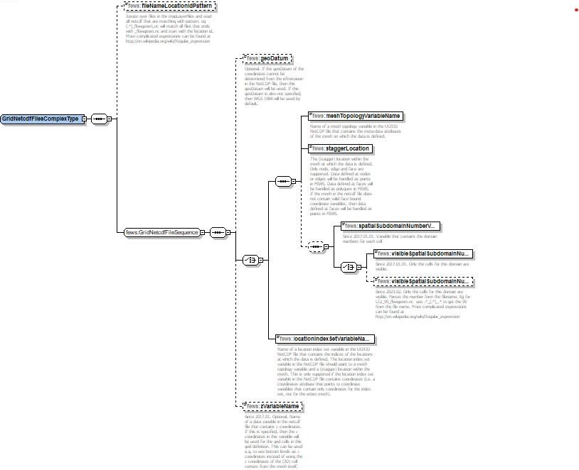
file
Name of a UGRID NetCDF file in the map layer files folder or a full absolute path to a UGRID NetCDF file. The file must have extension ".nc".
fileNameLocationIdPattern
Iterate over files in the mapLayerFiles and read all netcdf that are matching with pattern. eg (.*)_flowgeom\.nc will match all files that ends with _flowgeom.nc and start with the location id. More complicated expressions can be found at http://en.wikipedia.org/wiki/Regular_expression
geoDatum
Optional. If the geoDatum of the coordinates cannot be determined from the infromation in the NetCDF file, then this geoDatum will be used. If this geoDatum is also not specified, then WGS 1984 will be used by default.
meshTopologyVariableName
Name of a mesh topology variable in the UGRID NetCDF file that contains the meta-data attributes of the mesh on which the data is defined.
staggerLocation
The (stagger) location within the mesh at which the data is defined. Only node, edge and face are supported. Data defined at nodes or edges will be handled as points in FEWS. Data defined at faces will be handled as polygons in FEWS. If the mesh in the netcdf file does not contain valid face bound coordinate variables, then data defined at faces will be handled as points in FEWS.
locationIndexSetVariableName
Name of a location index set variable in the NetCDF file that contains the indices of the locations at which the data is defined. The location index set variable in the NetCDF file should point to a mesh topology variable and a (stagger) location within the mesh. This is only supported if the location index set variable in the NetCDF file contains coordinates (i.e. a coordinates attribute that points to coordinate variables that contain only coordinates for the index set, not for the entire mesh).
spatialSubdomainNumberVariable
Variable that contains the domain numbers for each cell.
visibleSpatialSubdomainNumber
Only the cells for this domain are visible. This functionality is important to handle overlapping grid cells in different domains.
visibleSpatialSubdomainNumberFileNamePattern
Only the cells for this domain are visible. This functionality is important to handle overlapping grid cells in different domains. Parses the number form the filename. E.g. for L12_99_flowgeom.nc use .*_(.*)_.* to get the 99 from the file name. More complicated expressions can be found at http://en.wikipedia.org/wiki/Regular_expression
Using a UGRID NetCDF file as unstructured grid definition
To import/export unstructured grid/flexible mesh data in Delft-FEWS, use a timeSeriesImport/ExportRun with type "NETCDF-CF_GRID" or use a generalAdapter import/exportNetcdfActivity. For this to work you need to add an irregular grid definition to the grids.xml configuration file. The easiest way to do this, is by using the option "netcdfFile" (see above) that refers to a NetCDF file that contains a UGRID mesh topology (and no data).
In an unstructured grid the data can be defined either on the nodes, the edges or the faces of the mesh (staggerLocations). Also see http://ugrid-conventions.github.io/ugrid-conventions/#data-defined-on-unstructured-meshes.
An example configuration can be downloaded here: example_unstructured_grid_config.zip. The example shows what is minimally needed to be present in the UGRID NetCDF file and how one can configure it in FEWS.
Each grid definition in grids.xml is valid for only one staggerLocation and this should match the staggerLocation of the data that you are going to import using the grid definition. The staggerLocation on which the data is defined can be deduced from the data variable in a netcdf file that contains the data to import. The data variable (e.g. "water_level") has an attribute called "location" and a dimension (e.g. nmesh2d_face) that both indicate its staggerLocation. In the grid geometry choose the corresponding staggerLocation. If you want to import different data variables that are defined on different staggerLocations in the same mesh, then you will have to create separate grid definitions for different staggerLocations using the same mesh from the same netcdf file, e.g.:
<irregular locationId="SFBayFM_data_on_faces">
    <netcdfFile>
        <file>sfbay_flowgeom.nc</file>
        <geoDatum>UTM10N</geoDatum>
        <meshTopologyVariableName>mesh2d</meshTopologyVariableName>
        <staggerLocation>face</staggerLocation>
    </netcdfFile>
</irregular>
<irregular locationId="SFBayFM_data_on_nodes">
    <netcdfFile>
        <file>sfbay_flowgeom.nc</file>
        <geoDatum>UTM10N</geoDatum>
        <meshTopologyVariableName>mesh2d</meshTopologyVariableName>
        <staggerLocation>node</staggerLocation>
    </netcdfFile>
</irregular>
D-Flow FM (Dutch: D-HYDRO)
It is possible to use a D-Flow flexible mesh (D-Flow FM) flowgeom UGRID NetCDF file, produced by a D-Flow FM model run, as grid definition in Delft-FEWS. If your D-Flow FM model run does not produce a flowgeom file, then add the following line in the D-Flow FM .mdu file in the output section, e.g.:
[output]
...
FlowGeomFile    = f34_flowgeom.nc    # *_flowgeom.nc Flow geometry file in NetCDF format.
...
The produced flowgeom file must be in UGRID 1.0 NetCDF format. Therefore you must use MapFormat = 4 in the D-Flow FM .mdu file in the output section:
[output]
...
MapFormat    = 4    # Map file format, 1: netCDF, 2: Tecplot, 3: netCFD and Tecplot, 4: NetCDF-UGRID
...
The flowgeom file format will match the configured map file format. If MapFormat is set to 4, then D-Flow FM will produce a valid UGRID file. With MapFormat set to 1 it will produce a format that looks very much like UGRID, but is not the same. Delft-FEWS can only use valid UGRID files. Using MapFormat 1 files with Delft-FEWS may cause problems.
If you have set MapFormat = 4, but the flowgeom file produced by D-Flow FM still causes errors in Delft-FEWS, then you may need to update to a newer version of DFlow-FM (1.2.2 or later). Note that in that case, you can manually create a valid flowgeom from the map file by removing all variables that depend on time from the netcdf file. This can be done using the third party command line tool nccopy, using a command like this (with uppercase -V):
nccopy -V mesh2d,wgs84,mesh2d_node_x,mesh2d_node_y,mesh2d_node_z,mesh2d_edge_nodes,mesh2d_edge_x,mesh2d_edge_y,mesh2d_edge_x_bnd,mesh2d_edge_y_bnd,mesh2d_face_nodes,mesh2d_face_x,mesh2d_face_y,mesh2d_face_x_bnd,mesh2d_face_y_bnd,mesh2d_FlowElem_ba,mesh2d_FlowElem_bl,mesh2d_edge_type map.nc flowgeom.nc
The tool nccopy is part of the NetCDF library binary distribution.
Config Examples
<irregular locationId="meshLocation">
	<netcdfFile>
		<file>simplebox_hex7_map.nc</file>
		<meshTopologyVariableName>insert_mesh_variable_name_here</meshTopologyVariableName>
		<staggerLocation>face</staggerLocation>
	</netcdfFile>
</irregular>
<irregular locationId="Swan2D_G2_cellcenters">
	<rows>1318</rows>
	<columns>317</columns>
	<esriShapeFile>
		<file>swan2D_G2_cellcenters.shp</file>
		<geoDatum>WGS 1984</geoDatum>
		<x>%X%</x>
		<y>%Y%</y>
	</esriShapeFile>
</irregular>
<irregular locationId="Swan2D_G2_cellcenters">
	<rows>1318</rows>
	<columns>317</columns>
	<esriShapeFile>
		<file>swan2D_G2_cellcenters.shp</file>
		<projectionFileAvailable>true</projectionFileAvailable>
		<x>%X%</x>
		<y>%Y%</y>
	</esriShapeFile>
</irregular>
<irregular locationId="Grid_Waqua_Zeedelta">
    <rows>1539</rows>
    <columns>501</columns>
    <csvFile>
        <file>Grid_Waqua_Zeedelta.csv</file>
        <geoDatum>Rijks Driehoekstelsel</geoDatum>
        <x>%X%</x>
        <y>%Y%</y>
    </csvFile>
</irregular>
<regular locationId="KNMI-HIRLAM-V70">
	<description>grid def. for KNMI-HIRLAM v7.0 with rotated pole</description>
	<rows>226</rows>
	<columns>136</columns>
	<rotatedSouthPole>
		<latitude>-30</latitude>
		<longitude>-15</longitude>
	</rotatedSouthPole>
	<gridCorners>
		<geoDatum>WGS 1984</geoDatum>
		<upperLeft>
			<x>-30.8688</x>
			<y>79.63847</y>
		</upperLeft>
		<lowerRight>
			<x>10.29617</x>
			<y>26.065</y>
		</lowerRight>
	</gridCorners>
</regular>
<regular locationId="WRF_CWB_Grid">
	<description>grid def. for imported WRF_CWB data</description>
	<rows>178</rows>
	<columns>148</columns>
	<geoDatum>WGS 1984</geoDatum>
	<firstCellCenter>
		<x>117.358656</x>
		<y>28.752274</y>
	</firstCellCenter>
	<xCellSize>0.048912529</xCellSize>
	<yCellSize>0.048912529</yCellSize>
</regular>
<regular locationId="QPF_LR">
		<description>QPF Grid for Long RangeABRFC</description>
	<rows>689</rows>
	<columns>1073</columns>
	<lambertConformalConic>
		<originLatitude>25.0</originLatitude>
		<originLongitude>265.0</originLongitude>
		<firstStandardParallelLatitude>25.0</firstStandardParallelLatitude>
		<secondStandardParallelLatitude>25.0</secondStandardParallelLatitude>
	</lambertConformalConic>
	<gridCorners>
		<geoDatum>WGS 1984</geoDatum>
		<upperLeft>
			<x>-130.13937712795388</x>
			<y>49.958437615088435</y>
			<z>0.0</z>
		</upperLeft>
		<lowerRight>
			<x>-69.19419381895221</x>
			<y>20.30332235930985</y>
			<z>0.0</z>
		</lowerRight>
	</gridCorners>
</regular>
<regular locationId="QPF">
	<description>QPF Grid for ABRFC</description>
	<rows>159</rows>
	<columns>335</columns>
	<polarStereographic>
		<originLatitude>90.0</originLatitude>
		<originLongitude>-105.0</originLongitude>
		<scaleAtOrigin>0.933</scaleAtOrigin>
		<equatorRadius>6367470.0</equatorRadius>
		<poleRadius>6367470.0</poleRadius>
	</polarStereographic>
	<gridCorners>
		<geoDatum>WGS 1984</geoDatum>
		<upperLeft>
			<x>-106.67471389477944</x>
			<y>39.37455858318055</y>
			<z>0.0</z>
		</upperLeft>
		<lowerRight>
			<x>-92.34455929643786</x>
			<y>32.390342856654044</y>
			<z>0.0</z>
		</lowerRight>
	</gridCorners>
</regular>
Generating XML
For NetCDF and GRIB files you can generate the grids.xml with F12>Clipboard>Copy grib geometry form file
1 Comment
Onno van den Akker
09-02-2010TODO,
describe new features,
debug menu F12 copy grid geometry, attach shape/dbf files, attach ascii grid files for elevation, rotated (north / south) pole, lambert conformal conic, rotated Cartesian.