Topology.Naming conventions for geometrical elements.Inspired by Wikipedia's definition of network topology, we define the mesh topology here as the interconnection of various geometrical elements of the mesh. The pure interconnectivity is independent of georeferencing the individual geometrical elements, but for the practical applications for which we are defining this CF extension, we'll always add coordinate data. Within a mesh, one can distinguish 0-, 1-, 2- and 3-dimensional elements. We need some names to identify these four types of elements; after discussion we propose the following names: Dimensionality | Proposed Name | Comments |
|---|
0 | node | A point, a coordinate pair or triplet: the most basic element of the topology.
The word node seems to be more commonly used than the alternative "vertex". | 1 | edge | A line or curve bounded by two nodes. | 2 | face | A plane or surface enclosed by a set of edges.
In a 2D horizontal application one may consider the word "polygon", but in the hierarchy of elements the word face is most common. | 3 | volume | A volume enclosed by a set of faces. |
 In favor of simpler code for interpreting compliant files, we have dropped to use of the In favor of simpler code for interpreting compliant files, we have dropped to use of the locations attribute which allowed the user to specify his/her own names for nodes, edges, faces and volumes.
1D network topology.The topology information is stored as attributes to a dummy variable (in the example below called "Mesh1") with cf_role mesh_topology. Required topology attributes | Value |
|---|
cf_role | mesh_topology | topology_dimension | 1 | node_coordinates | edge_node_connectivity | Optional attributes |
|---|
edge_coordinates |
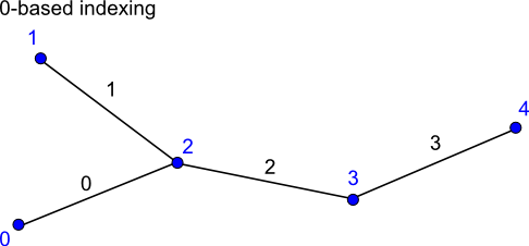
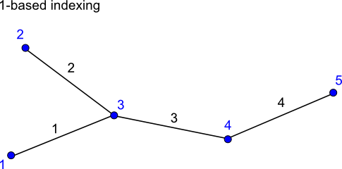
The attribute topology_dimension indicates the highest dimensionality of the geometric elements; for a 1D network this should be 1. The attribute node_coordinates points to the auxiliary coordinate variables representing the node locations (latitude, longitude, and optional elevation or other coordinates). These auxiliary coordinate variables will have length nNodes. The attribute edge_node_connectivity points to an index variable identifying for every edge to the indices of its begin and end nodes. The connectivity array will thus be a matrix of size nEdges x 2. For the indexing one may use either 0- or 1-based indexing; the convention used should be specified using a start_index attribute to the index variable (i.e. Mesh1_edge_nodes in the example below). Consistent with the CF-conventions compression option, the connectivity indices are 0-based by default. The option to support both 0- and 1-based indexing was introduced to be able to support existing files with 1-based index tables using ncML. See this section on 0-/1-based indexing for more details. The mesh_topology may optionally include an edge_coordinates attribute which points to the auxiliary coordinate variables associated with the characteristic location of the edge (commonly the midpoint). These auxiliary coordinate variables will have length nEdges, and may have in turn a bounds attribute that specifies the bounding coordinates of the edge (thereby duplicating the data in the node_coordinates variables). This use of the bounds attribute is consistent with the CF-convention on the use of bounds for multi-dimensional coordinate variables with p-sided cells, but it may not strictly be supported by the CF-convention right now.  Image Added Image Added
Example: | Code Block |
|---|
dimensions:
        nMesh1_node = 5 ; // nNodes
        nMesh1_edge = 4 ; // nEdges

        Two = 2;

variables:
// Mesh topology
        integer Mesh1 ;
                Mesh1:cf_role = "mesh_topology" ;
                Mesh1:long_name = "Topology data of 1D network" ;
                Mesh1:topology_dimension = 1 ;
                Mesh1:node_coordinates = "Mesh1_node_x Mesh1_node_y" ;
                Mesh1:edge_node_connectivity = "Mesh1_edge_nodes" ;
                Mesh1:edge_coordinates = "Mesh1_edge_x Mesh1_edge_y" ; // optional attribute
        integer Mesh1_edge_nodes(nMesh1_edge, Two) ;
                Mesh1_edge_nodes:cf_role = "edge_node_connectivity" ;
                Mesh1_edge_nodes:long_name = "Maps every edge/link to the two nodes that it connects." ;
                Mesh1_edge_nodes:start_index = 1 ;

// Mesh node coordinates
        double Mesh1_node_x(nMesh1_node) ;
                Mesh1_node_x:standard_name = "longitude" ;
                Mesh1_node_x:long_name = "Longitude of 1D network nodes." ;
                Mesh1_node_x:units = "degrees_east" ;
        double Mesh1_node_y(nMesh1_node) ;
                Mesh1_node_y:standard_name = "latitude" ;
                Mesh1_node_y:long_name = "Latitude of 1D network nodes." ;
                Mesh1_node_y:units = "degrees_north" ;

// Optional mesh edge coordinate variables
        double Mesh1_edge_x(nMesh1_edge) ;
                Mesh1_edge_x:standard_name = "longitude" ;
                Mesh1_edge_x:long_name = "Characteristic longitude of 1D network edge (e.g. midpoint of the edge)." ;
                Mesh1_edge_x:units = "degrees_east" ;
                Mesh1_edge_x:bounds = "Mesh1_edge_xbnds" ;
        double Mesh1_edge_y(nMesh1_edge) ;
                Mesh1_edge_y:standard_name = "latitude" ;
                Mesh1_edge_y:long_name = "Characteristic latitude of 1D network edge (e.g. midpoint of the edge)." ;
                Mesh1_edge_y:units = "degrees_north" ;
                Mesh1_edge_y:bounds = "Mesh1_edge_ybnds" ;
        double Mesh1_edge_xbnds(nMesh1_edge,Two) ;
                Mesh1_edge_xbnds:standard_name = "longitude" ;
                Mesh1_edge_xbnds:long_name = "Longitude bounds of 1D network edge (i.e. begin and end longitude)." ;
                Mesh1_edge_xbnds:units = "degrees_east" ;
        double Mesh1_edge_ybnds(nMesh1_edge,Two) ;
                Mesh1_edge_ybnds:standard_name = "latitude" ;
                Mesh1_edge_ybnds:long_name = "Latitude bounds of 1D network edge (i.e. begin and end latitude)." ;
                Mesh1_edge_ybnds:units = "degrees_north" ;
|
2D triangular mesh topology.The topology information is stored as attributes to a dummy variable (in the example below called "Mesh2") with cf_role mesh_topology. Required topology attributes | Value |
|---|
cf_role | mesh_topology | topology_dimension | 2 | node_coordinates | face_node_connectivity | Optionally required attributes* |
|---|
edge_node_connectivity | Optional attributes |
|---|
face_edge_connectivity | face_face_connectivity | face_coordinates | edge_coordinates |
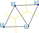
*The "Optionally required" attribute edge_node_connectivity is required only if you want to store data on the edges (i.e. if you mind the numbering order of the edges). The attribute topology_dimension indicates the highest dimensionality of the geometric elements; for a 2-dimensional (triangular) mesh this should be 2. The attribute node_coordinates points to the auxiliary coordinate variables representing the node locations (latitude, longitude, and optional elevation or other coordinates). These auxiliary coordinate variables will have length nNodes. The attribute face_node_connectivity points to an index variable identifying for every face (here consistently triangle) the indices of its three corner nodes. The corner nodes should be specified in anticlockwise (also referred to as counterclockwise) direction as viewed from above (consistent with the CF-convention for bounds of p-sided cells. The connectivity array will thus be a matrix of size nFaces x 3. For the indexing one may use either 0- or 1-based indexing; the convention used should be specified using a start_index attribute to the index variable (i.e. Mesh2_face_nodes in the example below). Consistent with the CF-conventions compression option, the connectivity indices are 0-based by default. See this section on 0-/1-based indexing for more details. In case you want to define variables on the edges of the triangular mesh topology you need to specify the edge_node_connectivity attribute to map edges to nodes. Although the face to node mapping implicitly also defines the location of the edges, it does not specify the global numbering of the edges. Again the indexing convention of edge_node_connectivity should be specified using the start_index attribute to the index variable (i.e. Mesh2_edge_nodes in the example below) and 0-based indexing is the default. Optionally the topology may have the following attributes: face_edge_connectivity pointing to an index variable identifying for every face (here consistently triangle) the indices of its three edges. The edges should be specified in anticlockwise direction as viewed from above. This connectivity array will thus be a matrix of size nFaces x 3. Again the indexing convention of face_edge_connectivity should be specified using the start_index attribute to the index variable (i.e. Mesh2_face_edges in the example below) and 0-based indexing is the default.face_face_connectivity pointing to an index variable identifying pairs of faces (here consistently triangle) that share an edge, i.e. are neighbors. TODO: CHECK DEFINITION This connectivity array will thus be a matrix of size nFacePairs x 2. Again the indexing convention of face_face_connectivity should be specified using the start_index attribute to the index variable (i.e. Mesh2_face_links in the example below) and 0-based indexing is the default.face_coordinates and/or edge_coordinates pointing to the auxiliary coordinate variables associated with the characteristic location of the faces and edges. These auxiliary coordinate variables will have length nFaces and nEdges respectively, and may have in turn a bounds attribute that specifies the bounding coordinates of the face or edge (thereby duplicating the data in the node_coordinates variables).
 Image Added Image Added
Example: | Code Block |
|---|
dimensions:
        nMesh2_node = 4 ; // nNodes
        nMesh2_edge = 5 ; // nEdges
        nMesh2_face = 2 ; // nFaces
        nMesh2_face_links = 1 ; // nFacePairs

        Two = 2 ;
        Three = 3 ;

variables:
// Mesh topology
        integer Mesh2 ;
                Mesh2:cf_role = "mesh_topology" ;
                Mesh2:long_name = "Topology data of 2D unstructured mesh" ;
                Mesh2:topology_dimension = 2 ;
                Mesh2:node_coordinates = "Mesh2_node_x Mesh2_node_y" ;
                Mesh2:face_node_connectivity = "Mesh2_face_nodes" ;
                Mesh2:edge_node_connectivity = "Mesh2_edge_nodes" ; // attribute required if variables will be defined on edges
                Mesh2:edge_coordinates = "Mesh2_edge_x Mesh2_edge_y" ; // optional attribute (requires edge_node_connectivity)
                Mesh2:face_coordinates = "Mesh2_face_x Mesh2_face_y" ; // optional attribute
                Mesh2:face_edge_connectivity = "Mesh2_face_edges" ; // optional attribute (requires edge_node_connectivity)
                Mesh2:face_face_connectivity = "Mesh2_face_links" ; // optional attribute
        integer Mesh2_face_nodes(nMesh2_face, Three) ;
                Mesh2_face_nodes:cf_role = "face_node_connectivity" ;
                Mesh2_face_nodes:long_name = "Maps every triangular face to its three corner nodes." ;
                Mesh2_face_nodes:start_index = 1 ;
        integer Mesh2_edge_nodes(nMesh2_edge, Two) ;
                Mesh2_edge_nodes:cf_role = "edge_node_connectivity" ;
                Mesh2_edge_nodes:long_name = "Maps every edge to the two nodes that it connects." ;
                Mesh2_edge_nodes:start_index = 1 ;

// Optional mesh topology variables
        integer Mesh2_face_edges(nMesh2_face, Three) ;
                Mesh2_face_edges:cf_role = "face_edge_connectivity" ;
                Mesh2_face_edges:long_name = "Maps every triangular face to its three edges." ;
                Mesh2_face_edges:start_index = 1 ;
        integer Mesh2_face_links(nMesh2_face_links, Two) ;
                Mesh2_face_links:cf_role = "face_face_connectivity" ;
                Mesh2_face_links:long_name = "Indicates pairs of (triangular) faces that share an edge." ;
                Mesh2_face_nodes:start_index = 1 ;

// Mesh node coordinates
        double Mesh2_node_x(nMesh2_node) ;
                Mesh2_node_x:standard_name = "longitude" ;
                Mesh2_node_x:long_name = "Longitude of 2D mesh nodes." ;
                Mesh2_node_x:units = "degrees_east" ;
        double Mesh2_node_y(nMesh2_node) ;
                Mesh2_node_y:standard_name = "latitude" ;
                Mesh2_node_y:long_name = "Latitude of 2D mesh nodes." ;
                Mesh2_node_y:units = "degrees_north" ;

// Optional mesh face and edge coordinate variables
        double Mesh2_face_x(nMesh2_face) ;
                Mesh2_face_x:standard_name = "longitude" ;
                Mesh2_face_x:long_name = "Characteristics longitude of 2D mesh triangle (e.g. circumcenter coordinate)." ;
                Mesh2_face_x:units = "degrees_east" ;
        double Mesh2_face_y(nMesh2_face) ;
                Mesh2_face_y:standard_name = "latitude" ;
                Mesh2_face_y:long_name = "Characteristics latitude of 2D mesh triangle (e.g. circumcenter coordinate)." ;
                Mesh2_face_y:units = "degrees_north" ;
        double Mesh2_edge_x(nMesh2_edge) ;
                Mesh2_edge_x:standard_name = "longitude" ;
                Mesh2_edge_x:long_name = "Characteristic longitude of 2D mesh edge (e.g. midpoint of the edge)." ;
                Mesh2_edge_x:units = "degrees_east" ;
        double Mesh2_edge_y(nMesh2_edge) ;
                Mesh2_edge_y:standard_name = "latitude" ;
                Mesh2_edge_y:long_name = "Characteristic latitude of 2D mesh edge (e.g. midpoint of the edge)." ;
                Mesh2_edge_y:units = "degrees_north" ;
|
2D flexible mesh (mixed triangles, quadrilaterals, etc.) topology.The case of a 2D mesh with mixed face sizes is identical to the 2D triangular mesh discussed above with the exception that not all faces have the same number of nodes. To support this variability we may use in the future a ragged array, but here we propose to use _FillValue to indicate faces with smaller number of nodes than the arrays allow. The topology information is stored as attributes to a dummy variable (in the example below called "Mesh2") with cf_role mesh_topology. Required topology attributes | Value |
|---|
cf_role | mesh_topology | topology_dimension | 2 | node_coordinates | face_node_connectivity | Optionally required attributes* |
|---|
edge_node_connectivity | Optional attributes |
|---|
face_edge_connectivity | face_face_connectivity | face_coordinates | edge_coordinates |
*The "Optionally required" attribute edge_node_connectivity is required only if you want to store data on the edges (i.e. if you mind the numbering order of the edges). The attribute topology_dimension indicates the highest dimensionality of the geometric elements; for a 2-dimensional mesh this should be 2. The attribute node_coordinates points to the auxiliary coordinate variables representing the node locations (latitude, longitude, and optional elevation or other coordinates). These auxiliary coordinate variables will have length nNodes. The attribute face_node_connectivity points to an index variable identifying for every face the indices of its corner nodes. The corner nodes should be specified in anticlockwise direction as viewed from above (consistent with the CF-convention for bounds of p-sided cells. The connectivity array will be a matrix of size nFaces x MaxNumNodesPerFace; if a face has less corner nodes than MaxNumNodesPerFace then the last node indices shall be equal to _FillValue (which should obviously be larger than the number of nodes in the mesh). For the indexing one may use either 0- or 1-based indexing; the convention used should be specified using a start_index attribute to the index variable (i.e. Mesh2_face_nodes in the example below). Consistent with the CF-conventions compression option, the connectivity indices are 0-based by default. See this section on 0-/1-based indexing for more details. In case you want to define variables on the edges of the 2D mesh topology you need to specify the edge_node_connectivity attribute to map edges to nodes. Although the face to node mapping implicitly also defines the location of the edges, it does not specify the global numbering of the edges. Again the indexing convention of edge_node_connectivity should be specified using the start_index attribute to the index variable (i.e. Mesh2_edge_nodes in the example below) and 0-based indexing is the default. Optionally the topology may have the following attributes: face_edge_connectivity pointing to an index variable identifying for every face the indices of its edges. The edges should be specified in anticlockwise direction as viewed from above. This connectivity array will be a matrix of size nFaces x MaxNumNodesPerFace. Again, if a face has less corners/edges than MaxNumNodesPerFace then the last edge indices shall be equal to _FillValue, and the indexing convention of face_edge_connectivity should be specified using the start_index attribute to the index variable (i.e. Mesh2_face_edges in the example below) and 0-based indexing is the default.face_face_connectivity pointing to an index variable identifying pairs of faces that share an edge, i.e. are neighbors. TODO: CHECK DEFINITION This connectivity array will thus be a matrix of size nFacePairs x 2. Again the indexing convention of face_face_connectivity should be specified using the start_index attribute to the index variable (i.e. Mesh2_face_links in the example below) and 0-based indexing is the default.face_coordinates and/or edge_coordinates pointing to the auxiliary coordinate variables associated with the characteristic location of the faces and edges. These auxiliary coordinate variables will have length nFaces and nEdges respectively, and may have in turn a bounds attribute that specifies the bounding coordinates of the face or edge (thereby duplicating the data in the node_coordinates variables).
The use of _FillValue to indicate faces with less nodes than MaxNumNodesPerFace extends to the coordinate bounds variables; this is an extension of the current convention.  Image Added Image Added
Example: | Code Block |
|---|
dimensions:
        nMesh2_node = 5 ; // nNodes
        nMesh2_edge = 6 ; // nEdges
        nMesh2_face = 2 ; // nFaces
        nMesh2_face_links = 1 ; // nFacePairs
        nMaxMesh2_face_nodes = 4 ; // MaxNumNodesPerFace

        Two = 2 ;

variables:
// Mesh topology
        integer Mesh2 ;
                Mesh2:cf_role = "mesh_topology" ;
                Mesh2:long_name = "Topology data of 2D unstructured mesh" ;
                Mesh2:topology_dimension = 2 ;
                Mesh2:node_coordinates = "Mesh2_node_x Mesh2_node_y" ;
                Mesh2:face_node_connectivity = "Mesh2_face_nodes" ;
                Mesh2:edge_node_connectivity = "Mesh2_edge_nodes" ; // attribute required if variables will be defined on edges
                Mesh2:edge_coordinates = "Mesh2_edge_x Mesh2_edge_y" ; // optional attribute (requires edge_node_connectivity)
                Mesh2:face_coordinates = "Mesh2_face_x Mesh2_face_y" ; // optional attribute
                Mesh2:face_edge_connectivity = "Mesh2_face_edges" ; // optional attribute (requires edge_node_connectivity)
                Mesh2:face_face_connectivity = "Mesh2_face_links" ; // optional attribute
        integer Mesh2_face_nodes(nMesh2_face, nMaxMesh2_face_nodes) ;
                Mesh2_face_nodes:cf_role = "face_node_connectivity" ;
                Mesh2_face_nodes:long_name = "Maps every face to its corner nodes." ;
                Mesh2_face_nodes:_FillValue = 999999 ;
                Mesh2_face_nodes:start_index = 1 ;
        integer Mesh2_edge_nodes(nMesh2_edge, Two) ;
                Mesh2_edge_nodes:cf_role = "edge_node_connectivity" ;
                Mesh2_edge_nodes:long_name = "Maps every edge to the two nodes that it connects." ;
                Mesh2_edge_nodes:start_index = 1 ;

// Optional mesh topology variables
        integer Mesh2_face_edges(nMesh2_face, nMaxMesh2_face_nodes) ;
                Mesh2_face_edges:cf_role = "face_edge_connectivity" ;
                Mesh2_face_edges:long_name = "Maps every face to its edges." ;
                Mesh2_face_edges:_FillValue = 999999 ;
                Mesh2_face_edges:start_index = 1 ;
        integer Mesh2_face_links(nMesh2_face_links, Two) ;
                Mesh2_face_links:cf_role = "face_face_connectivity" ;
                Mesh2_face_links:long_name = "Indicates which faces are neighbors." ;
                Mesh2_face_links:start_index = 1 ;

// Mesh node coordinates
        double Mesh2_node_x(nMesh2_node) ;
                Mesh2_node_x:standard_name = "longitude" ;
                Mesh2_node_x:long_name = "Longitude of 2D mesh nodes." ;
                Mesh2_node_x:units = "degrees_east" ;
        double Mesh2_node_y(nMesh2_node) ;
                Mesh2_node_y:standard_name = "latitude" ;
                Mesh2_node_y:long_name = "Latitude of 2D mesh nodes." ;
                Mesh2_node_y:units = "degrees_north" ;

// Optional mesh face and edge coordinate variables
        double Mesh2_face_x(nMesh2_face) ;
                Mesh2_face_x:standard_name = "longitude" ;
                Mesh2_face_x:long_name = "Characteristics longitude of 2D mesh face." ;
                Mesh2_face_x:units = "degrees_east" ;
                Mesh2_face_x:bounds = "Mesh2_face_xbnds" ;
        double Mesh2_face_y(nMesh2_face) ;
                Mesh2_face_y:standard_name = "latitude" ;
                Mesh2_face_y:long_name = "Characteristics latitude of 2D mesh face." ;
                Mesh2_face_y:units = "degrees_north" ;
                Mesh2_face_y:bounds = "Mesh2_face_ybnds" ;
        double Mesh2_face_xbnds(nMesh2_face,nMaxMesh2_face_nodes) ;
                Mesh2_face_xbnds:standard_name = "longitude" ;
                Mesh2_face_xbnds:long_name = "Longitude bounds of 2D mesh face (i.e. corner coordinates)." ;
                Mesh2_face_xbnds:units = "degrees_east" ;
                Mesh2_face_xbnds:_FillValue = 9.9692099683868690E36;
        double Mesh2_face_ybnds(nMesh2_face,nMaxMesh2_face_nodes) ;
                Mesh2_face_ybnds:standard_name = "latitude" ;
                Mesh2_face_ybnds:long_name = "Latitude bounds of 2D mesh face (i.e. corner coordinates)." ;
                Mesh2_face_ybnds:units = "degrees_north" ;
                Mesh2_face_ybnds:_FillValue = 9.9692099683868690E36;
        double Mesh2_edge_x(nMesh2_edge) ;
                Mesh2_edge_x:standard_name = "longitude" ;
                Mesh2_edge_x:long_name = "Characteristic longitude of 2D mesh edge (e.g. midpoint of the edge)." ;
                Mesh2_edge_x:units = "degrees_east" ;
        double Mesh2_edge_y(nMesh2_edge) ;
                Mesh2_edge_y:standard_name = "latitude" ;
                Mesh2_edge_y:long_name = "Characteristic latitude of 2D mesh edge (e.g. midpoint of the edge)." ;
                Mesh2_edge_y:units = "degrees_north" ;
        // bounds variables for edges skipped
|
3D layered mesh topology.For a 3D layered unstructured mesh topology this proposal follows the approach of the existing CF-conventions for structured meshes: horizontal and vertical dimensions are treated separately. For the horizontal plane a 2D unstructured mesh topology is defined, which is extruded in the vertical direction by means of a vertical coordinate. The example below matches the example in the previous section combined with a vertical coordinate according CF-conventions. This example introduces also the attributes mesh and location on the 2D variables "Mesh2_surface" and "Mesh2_depth". For more information about these attributes see the data definition section below.  Image Added Image Added
Example: | Code Block |
|---|
dimensions:
        nMesh2_node = 6 ; // nNodes
        nMesh2_edge = 7 ; // nEdges
        nMesh2_face = 2 ; // nFaces
        nMesh2_face_links = 1 ; // nFacePairs
        nMaxMesh2_face_nodes = 4 ; // MaxNumNodesPerFace
        Mesh2_layers = 10 ;

        Two = 2 ;

variables:
// Mesh topology
        integer Mesh2 ;
                Mesh2:cf_role = "mesh_topology" ;
                Mesh2:long_name = "Topology data of 2D unstructured mesh" ;
                Mesh2:topology_dimension = 2 ;
                Mesh2:node_coordinates = "Mesh2_node_x Mesh2_node_y" ;
                Mesh2:face_node_connectivity = "Mesh2_face_nodes" ;
                Mesh2:edge_node_connectivity = "Mesh2_edge_nodes" ; // attribute required if variables will be defined on edges
                Mesh2:edge_coordinates = "Mesh2_edge_x Mesh2_edge_y" ; // optional attribute (requires edge_node_connectivity)
                Mesh2:face_coordinates = "Mesh2_face_x Mesh2_face_y" ; // optional attribute
                Mesh2:face_edge_connectivity = "Mesh2_face_edges" ; // optional attribute (requires edge_node_connectivity)
                Mesh2:face_face_connectivity = "Mesh2_face_links" ; // optional attribute
        integer Mesh2_face_nodes(nMesh2_face, nMaxMesh2_face_nodes) ;
                Mesh2_face_nodes:cf_role = "face_node_connectivity" ;
                Mesh2_face_nodes:long_name = "Maps every face to its corner nodes." ;
                Mesh2_face_nodes:_FillValue = 999999 ;
                Mesh2_face_nodes:start_index = 1 ;
        integer Mesh2_edge_nodes(nMesh2_edge, Two) ;
                Mesh2_edge_nodes:cf_role = "edge_node_connectivity" ;
                Mesh2_edge_nodes:long_name = "Maps every edge to the two nodes that it connects." ;
                Mesh2_edge_nodes:start_index = 1 ;

// Optional mesh topology variables
        integer Mesh2_face_edges(nMesh2_face, nMaxMesh2_face_nodes) ;
                Mesh2_face_edges:cf_role = "face_edge_connectivity" ;
                Mesh2_face_edges:long_name = "Maps every face to its edges." ;
                Mesh2_face_edges:_FillValue = 999999 ;
                Mesh2_face_edges:start_index = 1 ;
        integer Mesh2_face_links(nMesh2_face_links, Two) ;
                Mesh2_face_links:cf_role = "face_face_connectivity" ;
                Mesh2_face_links:long_name = "Indicates which faces are neighbors." ;
                Mesh2_face_links:start_index = 1 ;

// Mesh node coordinates
        double Mesh2_node_x(nMesh2_node) ;
                Mesh2_node_x:standard_name = "longitude" ;
                Mesh2_node_x:long_name = "Longitude of 2D mesh nodes." ;
                Mesh2_node_x:units = "degrees_east" ;
        double Mesh2_node_y(nMesh2_node) ;
                Mesh2_node_y:standard_name = "latitude" ;
                Mesh2_node_y:long_name = "Latitude of 2D mesh nodes." ;
                Mesh2_node_y:units = "degrees_north" ;

// Optional mesh face and edge coordinate variables
        double Mesh2_face_x(nMesh2_face) ;
                Mesh2_face_x:standard_name = "longitude" ;
                Mesh2_face_x:long_name = "Characteristics longitude of 2D mesh face." ;
                Mesh2_face_x:units = "degrees_east" ;
                Mesh2_face_x:bounds = "Mesh2_face_xbnds" ;
        double Mesh2_face_y(nMesh2_face) ;
                Mesh2_face_y:standard_name = "latitude" ;
                Mesh2_face_y:long_name = "Characteristics latitude of 2D mesh face." ;
                Mesh2_face_y:units = "degrees_north" ;
                Mesh2_face_y:bounds = "Mesh2_face_ybnds" ;
        double Mesh2_face_xbnds(nMesh2_face,nMaxMesh2_face_nodes) ;
                Mesh2_face_xbnds:standard_name = "longitude" ;
                Mesh2_face_xbnds:long_name = "Longitude bounds of 2D mesh face (i.e. corner coordinates)." ;
                Mesh2_face_xbnds:units = "degrees_east" ;
                Mesh2_face_xbnds:_FillValue = 9.9692099683868690E36;
        double Mesh2_face_ybnds(nMesh2_face,nMaxMesh2_face_nodes) ;
                Mesh2_face_ybnds:standard_name = "latitude" ;
                Mesh2_face_ybnds:long_name = "Latitude bounds of 2D mesh face (i.e. corner coordinates)." ;
                Mesh2_face_ybnds:units = "degrees_north" ;
                Mesh2_face_ybnds:_FillValue = 9.9692099683868690E36;
        double Mesh2_edge_x(nMesh2_edge) ;
                Mesh2_edge_x:standard_name = "longitude" ;
                Mesh2_edge_x:long_name = "Characteristic longitude of 2D mesh edge (e.g. midpoint of the edge)." ;
                Mesh2_edge_x:units = "degrees_east" ;
        double Mesh2_edge_y(nMesh2_edge) ;
                Mesh2_edge_y:standard_name = "latitude" ;
                Mesh2_edge_y:long_name = "Characteristic latitude of 2D mesh edge (e.g. midpoint of the edge)." ;
                Mesh2_edge_y:units = "degrees_north" ;
        // bounds variables for edges skipped

// Vertical coordinate
        double Mesh2_layers(Mesh2_layers) ;
                Mesh2_layers:standard_name = "ocean_sigma_coordinate" ;
                Mesh2_layers:long_name = "sigma at layer midpoints" ;
                Mesh2_layers:positive = "up" ;
                Mesh2_layers:formula_terms = "sigma: Mesh2_layers eta: Mesh2_surface depth: Mesh2_depth" ;
        double Mesh2_depth(nMesh2_node) ;
                Mesh2_depth:standard_name = "sea_floor_depth_below_geoid" ;
                Mesh2_depth:units = "m" ;
                Mesh2_depth:positive = "down" ;
                Mesh2_depth:mesh = "Mesh2"
                Mesh2_depth:location = "node" ;
                Mesh2_depth:coordinates = "Mesh2_node_x Mesh2_node_y" ;
        double Mesh2_surface(nMesh2_node) ;
                Mesh2_surface:standard_name = "sea_surface_height_above_geoid" ;
                Mesh2_surface:units = "m" ;
                Mesh2_surface:mesh = "Mesh2"
                Mesh2_surface:location = "face" ;
                Mesh2_surface:coordinates = "Mesh2_face_x Mesh2_face_y" ;
|
fully 3D unstructured (i.e. non-layered) mesh topology.For a fully 3D unstructured mesh topology we extend the hierarchy of nodes, edges and faces to volumes. Contrary to layered case this type of mesh requires a fully 3D specification of the mesh; hence we not only need latitude and longitude coordinates but also some kind of elevation coordinate (this probably requires a new standard name). The topology information is stored as attributes to a dummy variable (in the example below called "Mesh3D") with cf_role mesh_topology. Required topology attributes | Value |
|---|
cf_role | mesh_topology | topology_dimension | 3 | node_coordinates | volume_node_connectivity | volume_shape_type | Optionally required attributes* |
|---|
face_node_connectivity | edge_node_connectivity | Optional attributes |
|---|
volume_edge_connectivity | volume_face_connectivity | volume_volume_connectivity | face_edge_connectivity | volume_coordinates | face_coordinates | edge_coordinates |
*The "Optionally required" attributes edge_node_connectivity and face_node_connectivity are required only if you want to store data on the edges or faces respectively (i.e. if you mind the numbering order of the edges/faces). The attribute topology_dimension indicates the highest dimensionality of the geometric elements; for a fully 3-dimensional unstructured mesh this should be 3. The attribute node_coordinates points to the auxiliary coordinate variables representing the node locations (latitude, longitude, elevation and optional other coordinates). These auxiliary coordinate variables will have length nNodes. The attribute volume_node_connectivity points to an index variable identifying for every volume the indices of its corner nodes. For faces in the horizontal plane, it was possible to prescribe the order of the nodes, but this is not possible for the nodes of generic 3D volumes. For this reason we introduce an additional attribute volume_shape_type which points to a flag variable that specifies for every volume its shape: flag_meaning name | description |
|---|
tetrahedron | pyramid with triangular base, 4 nodes | pyramid | pyramid with square base, a pentahedron, 5 nodes | wedge | prism with triangular base, a pentahedron, 6 nodes | hexahedron | distorted cube, 8 nodes |
These four volume shapes are the ones most commonly used. More shapes can be added; and if necessary, it's possible to add a generic shape type which allows for specification of the volume shape indirectly via volume_face_connectivity and face_node_connectivity variables. Such a generic shape is not included in this proposal since there is no practical need for such feature at this time. If all volumes have the same shape type, then the shape typed could be determined based on the number of nodes per volume. Another option could be to allow the volume_shape_type to specify the shape type directly rather than pointing to a variable. However, for the time being we assume that the currently proposed volume shape type variable doesn't have too much impact on the performance. The order in which the corner nodes of a volume are specified is fixed given its shape; this approach is common in 3D modeling, see e.g. this graph in the OpenFOAM documentation and PARAVIEW or VTK documentation. The volume_node_connectivity array will be a matrix of size nVolumes x MaxNumNodesPerVolume; if a volume has less corner nodes than MaxNumNodesPerVolume then the last node indices shall be equal to _FillValue (which should obviously be larger than the number of nodes in the mesh). For the indexing one may use either 0- or 1-based indexing; the convention used should be specified using a start_index attribute to the index variable (i.e. Mesh3D_vol_nodes in the example below). Consistent with the CF-conventions compression option, the connectivity indices are 0-based by default. See this section on 0-/1-based indexing for more details. In case you want to define variables on the faces or edges of the 3D mesh topology you need to specify the face_node_connectivity or edge_node_connectivity attribute, respectively, to map faces or edges to nodes. Although the volume to node mapping implicitly also defines the location of the faces and edges, it does not specify their global numbering. Again the indexing convention of face_node_connectivity and edge_node_connectivity should be specified using the start_index attribute to the index variable and 0-based indexing is the default. Optionally the topology may have the following attributes: volume_face_connectivity pointing to an index variable identifying for every volume the indices of its faces. The order in which the face indices should be specified is determined by the volume geometry type. This connectivity array will be a matrix of size nVolumes x MaxNumFacesPerVolume. If a volume has less faces than MaxNumFacesPerVolume then the last face indices shall be equal to _FillValue, and the indexing convention of volume_edge_connectivity should be specified using the start_index attribute to the index variable and 0-based indexing is the default.volume_edge_connectivity pointing to an index variable identifying for every volume the indices of its edges. The order in which the edge indices should be specified is determined by the volume geometry type. This connectivity array will be a matrix of size nVolumes x MaxNumEdgesPerVolume. Again, if a volume has less edges than MaxNumEdgesPerVolume then the last edge indices shall be equal to _FillValue, and the indexing convention of volume_edge_connectivity should be specified using the start_index attribute to the index variable and 0-based indexing is the default.volume_volume_connectivity pointing to an index variable identifying pairs of volumes that share a face, i.e. are neighbors. This connectivity array will thus be a matrix of size nVolumePairs x 2. As usual the indexing convention of volume_volume_connectivity should be specified using the start_index attribute to the index variable (i.e. Mesh3D_vol_links in the example below) and 0-based indexing is the default.face_edge_connectivity pointing to an index variable identifying for every face the indices of its edges. The edges should be specified in anticlockwise direction as viewed from above. This connectivity array will be a matrix of size nFaces x MaxNumNodesPerFace. As always, if a face has less corners/edges than MaxNumNodesPerFace then the last edge indices shall be equal to _FillValue, and the indexing convention of face_edge_connectivity should be specified using the start_index attribute to the index variable and 0-based indexing is the default.face_node_connectivity pointing to an index variable identifying for every face the indices of its nodes. The nodes should be specified in either clockwise or anticlockwise order. This connectivity array will be a matrix of size nFaces x MaxNumNodesPerFace. Again, if a face has less corners/edges than MaxNumNodesPerFace then the last node indices shall be equal to _FillValue, and the indexing convention of face_node_connectivity should be specified using the start_index attribute to the index variable and 0-based indexing is the default.volume_coordinates, face_coordinates and/or edge_coordinates pointing to the auxiliary coordinate variables associated with the characteristic location of the volumes, faces and edges. These auxiliary coordinate variables will have length nVolumes, nFaces and nEdges respectively, and may have in turn a bounds attribute that specifies the corner coordinates of the volume, face or edge (thereby duplicating the data in the node_coordinates variables). The order in which the corner coordinates of the volumes is given by the volume geometry type.
 Image Added Image Added
Example: | Code Block |
|---|
dimensions:
        nMesh3D_node = 12 ; // nNodes
        nMesh3D_edge = 23 ; // nEdges
        nMesh3D_face = 16 ; // nFaces
        nMesh3D_vol  = 4 ; // nVolumes
        nMesh3D_vol_links = 4 ; // nVolumePairs
        nMaxMesh3D_face_nodes = 4 ; // MaxNumNodesPerFace
        nMaxMesh3D_vol_nodes  = 8 ; // MaxNumNodesPerVolume
        nMaxMesh3D_vol_edges  = 12 ; // MaxNumEdgesPerVolume
        nMaxMesh3D_vol_faces  = 6 ; // MaxNumFacesPerVolume

        Two = 2 ;

variables:
// Mesh topology
        integer Mesh3D ;
                Mesh3D:cf_role = "mesh_topology" ;
                Mesh3D:long_name = "Topology data of 3D unstructured mesh" ;
                Mesh3D:topology_dimension = 3 ;
                Mesh3D:node_coordinates = "Mesh3D_node_x Mesh3D_node_y Mesh3D_node_z" ;
                Mesh3D:volume_shape_type = "Mesh3D_vol_types" ;
                Mesh3D:volume_node_connectivity = "Mesh3D_vol_nodes" ;
                Mesh3D:face_node_connectivity = "Mesh3D_face_nodes" ; // attribute required if variables will be defined on faces
                Mesh3D:edge_node_connectivity = "Mesh3D_edge_nodes" ; // attribute required if variables will be defined on edges
                Mesh3D:edge_coordinates = "Mesh3D_edge_x Mesh3D_edge_y Mesh3D_edge_z" ; // optional attribute (requires edge_node_connectivity)
                Mesh3D:face_coordinates = "Mesh3D_face_x Mesh3D_face_y Mesh3D_face_z" ; // optional attribute (requires face_node_connectivity)
                Mesh3D:volume_coordinates = "Mesh3D_vol_x Mesh3D_vol_y Mesh3D_vol_z" ; // optional attribute
                Mesh3D:volume_face_connectivity = "Mesh3D_vol_faces" ; // optional attribute (requires face_node_connectivity)
                Mesh3D:volume_edge_connectivity = "Mesh3D_vol_edges" ; // optional attribute (requires edge_node_connectivity)
                Mesh3D:face_edge_connectivity = "Mesh3D_face_edges" ; // optional attribute (requires face_node_connectivity and edge_node_connectivity)
                Mesh3D:volume_volume_connectivity = "Mesh3D_vol_links" ; // optional attribute
        integer Mesh3D_vol_types(nMesh3D_vol) ;
                Mesh3D_vol_types:cf_role = "volume_shape_type" ;
                Mesh3D_vol_types:long_name = "Specifies the shape of the individual volumes." ;
                Mesh3D_vol_types:flag_range = 0b, 2b ;
                Mesh3D_vol_types:flag_values = 0b, 1b, 2b ;
                Mesh3D_vol_types:flag_meanings = "tetrahedron wedge hexahedron" ;
        integer Mesh3D_vol_nodes(nMesh3D_vol, nMaxMesh3D_vol_nodes) ;
                Mesh3D_vol_nodes:cf_role = "volume_node_connectivity" ;
                Mesh3D_vol_nodes:long_name = "Maps every volume to its corner nodes." ;
                Mesh3D_vol_nodes:_FillValue = 999999 ;
                Mesh3D_vol_nodes:start_index = 1 ;

// Optional mesh topology variables
        integer Mesh3D_edge_nodes(nMesh3D_edge, Two) ;
                Mesh3D_edge_nodes:cf_role = "edge_node_connectivity" ;
                Mesh3D_edge_nodes:long_name = "Maps every edge to the two nodes that it connects." ;
                Mesh3D_edge_nodes:start_index = 1 ;
        integer Mesh3D_face_nodes(nMesh3D_face, nMaxMesh3D_face_nodes) ;
                Mesh3D_face_nodes:cf_role = "face_node_connectivity" ;
                Mesh3D_face_nodes:long_name = "Maps every face to its corner nodes." ;
                Mesh3D_face_nodes:_FillValue = 999999 ;
                Mesh3D_face_nodes:start_index = 1 ;
        integer Mesh3D_vol_faces(nMesh3D_vol, nMaxMesh3D_vol_faces) ;
                Mesh3D_vol_faces:cf_role = "volume_face_connectivity" ;
                Mesh3D_vol_faces:long_name = "Maps every volume to its faces." ;
                Mesh3D_vol_faces:_FillValue = 999999 ;
                Mesh3D_vol_faces:start_index = 1 ;
        integer Mesh3D_vol_edges(nMesh3D_vol, nMaxMesh3D_vol_edges) ;
Mesh3D_vol_edges:cf_role = "volume_edge_connectivity" |
|