netcdf test_map {
dimensions:
// dimensions for mesh 1
nMesh1_node = 3 _edge_nodes:start_index = 1 ;
// Mesh node coordinates
double Mesh1_node_x(nMesh1_node) ;
Mesh1_node_x:standard_name = "longitude" ;
Mesh1_node_x:long_name = "Longitude of 1D network nodes." ;
Mesh1_node_x:units = "degrees_east" ;
double Mesh1_node_y(nMesh1_node) ;
|
nMesh1_edge= 2;
nMaxMesh1_contour_ptsMesh1_node_y:standard_name = |
99nMesh1_cell=2;
nMesh1_interface2 ;
"Latitude of 1D network nodes." ;
|
//dimensionsformesh2
nMesh26"degrees_north" ;
// Optional mesh |
nMesh2_=7 ;nMesh2_face = 2 double Mesh1_edge_x(nMesh1_edge) ;
|
nMesh2_edge_nodes=7;
nMesh2_face_nodesMesh1_edge_x:standard_name = |
4nMesh2_face_links=1;
nMaxMesh2_face_nodes4;
"Characteristic longitude of 1D network edge (e.g. midpoint |
nMaxMesh2_contour_pts = 99 ;
//dimensionsformesh3
nMesh3_node6 nMesh3_edge=7;
nMesh3_face2"Mesh1_edge_xbnds" ;
double |
nMesh3nodes = 7nMesh3_face_nodes=4;
nMesh3_face_linksMesh1_edge_y:standard_name = |
1 nMaxMesh3_face_nodes=4;
nMaxMesh3_contour_pts99;
latitude of 1D network edge (e.g. midpoint of |
nMesh3_layer = 3 nMesh3_interface=4;
// common dimensionsMesh1_edge_y:units = "degrees_north" ;
|
Two=2;
time = UNLIMITED ; // (1 currently)
variables:
// Basic mesh data (coordinates independent of computational cells whatsoever)
= "Mesh1_edge_ybnds" ;
double Mesh1_ |
nodexnode nodexprojection_x_coordinate nodexnetnodal x-coordinateLongitude bounds of 1D network edge (i.e. begin and end longitude)." ; |
nodexm
double Mesh1_edge_ybnds(nMesh1_edge,Two) ;
|
Mesh1_node_x:bounds="Mesh1_node_contour_x";
double node_y(nMesh1_node) ;
Mesh1_node_yedge_ybnds:standard_name = " |
projection_y_coordinate nodeynetnodal y-coordinate" ;
Mesh1_node_y:units = "m" ; Latitude bounds of 1D network edge (i.e. begin and end latitude)." ;
Mesh1_ |
nodeyboundsMesh1_node_contour_y
double Mesh1_edge_x(nMesh1_edge) ;
Mesh1_edge_x:standard_name = "projection_x_coordinate" ;
Mesh1_edge_x:long_name = "Center coordinate of net link (velocity point)." ;
Mesh1_edge_x:units = "m" ;
double Mesh1_edge_y(nMesh1_edge) ;
Mesh1_edge_y:standard_name = "projection_y_coordinate" ;
Mesh1_edge_y:long_name = "Center coordinate of net link (velocity point)." ;
Mesh1_edge_y:units = "m" ;
double Mesh1_node_contour_x(nMesh1_node, nMaxMesh1_contour_pts) ;
Mesh1_node_contour_x:standard_name = "projection_x_coordinate" ;
Mesh1_node_contour_x:long_name = "List of x-points that form outline of flow volume" ; 2D triangular mesh topology.The topology information is stored as attributes to a dummy variable (in the example below called "Mesh2") with cf_role mesh_topology. Required topology attributes | Value |
|---|
cf_role | mesh_topology | topology_dimension | 2 | node_coordinates | face_node_connectivity | Optionally required attributes* |
|---|
edge_node_connectivity | Optional attributes |
|---|
face_edge_connectivity | face_face_connectivity | face_coordinates | edge_coordinates |
*The "Optionally required" attribute edge_node_connectivity is required only if you want to store data on the edges (i.e. if you mind the numbering order of the edges). The attribute topology_dimension indicates the highest dimensionality of the geometric elements; for a 2-dimensional (triangular) mesh this should be 2. The attribute node_coordinates points to the auxiliary coordinate variables representing the node locations (latitude, longitude, and optional elevation or other coordinates). These auxiliary coordinate variables will have length nNodes. The attribute face_node_connectivity points to an index variable identifying for every face (here consistently triangle) the indices of its three corner nodes. The corner nodes should be specified in anticlockwise (also referred to as counterclockwise) direction as viewed from above (consistent with the CF-convention for bounds of p-sided cells. The connectivity array will thus be a matrix of size nFaces x 3. For the indexing one may use either 0- or 1-based indexing; the convention used should be specified using a start_index attribute to the index variable (i.e. Mesh2_face_nodes in the example below). Consistent with the CF-conventions compression option, the connectivity indices are 0-based by default. See this section on 0-/1-based indexing for more details. In case you want to define variables on the edges of the triangular mesh topology you need to specify the edge_node_connectivity attribute to map edges to nodes. Although the face to node mapping implicitly also defines the location of the edges, it does not specify the global numbering of the edges. Again the indexing convention of edge_node_connectivity should be specified using the start_index attribute to the index variable (i.e. Mesh2_edge_nodes in the example below) and 0-based indexing is the default. Optionally the topology may have the following attributes: face_edge_connectivity pointing to an index variable identifying for every face (here consistently triangle) the indices of its three edges. The edges should be specified in anticlockwise direction as viewed from above. This connectivity array will thus be a matrix of size nFaces x 3. Again the indexing convention of face_edge_connectivity should be specified using the start_index attribute to the index variable (i.e. Mesh2_face_edges in the example below) and 0-based indexing is the default.face_face_connectivity pointing to an index variable identifying pairs of faces (here consistently triangle) that share an edge, i.e. are neighbors. TODO: CHECK DEFINITION This connectivity array will thus be a matrix of size nFacePairs x 2. Again the indexing convention of face_face_connectivity should be specified using the start_index attribute to the index variable (i.e. Mesh2_face_links in the example below) and 0-based indexing is the default.face_coordinates and/or edge_coordinates pointing to the auxiliary coordinate variables associated with the characteristic location of the faces and edges. These auxiliary coordinate variables will have length nFaces and nEdges respectively, and may have in turn a bounds attribute that specifies the bounding coordinates of the face or edge (thereby duplicating the data in the node_coordinates variables).
 Image Added Image Added
Example: | Code Block |
|---|
dimensions:
        nMesh2_node = 4 ; // nNodes
|
Mesh1_node_contour_x:units"m"double Mesh1_node_contour_y(nMesh1_node, nMaxMesh1_contour_pts)nMesh2_face = 2 ; // nFaces
nMesh2_face_links = 1 ; // nFacePairs
|
Mesh1_node_contour_y:standard_name"projection_y_coordinate"
Three = 3 ;
variables:
// Mesh topology
|
Mesh1_node_contour_y:units="m";Mesh1_node_contour_y:long_nameList of y-points that form outline of flow volume" ;
// Basic mesh topology
integer Mesh1_edge_nodes(nMesh1_edge, Two) ; mesh_topology" ;
Mesh2:long_name = "Topology data of 2D unstructured mesh" ;
|
Mesh1_edge_nodes:long_nameMesh2:topology_dimension = |
"links between two nodes" integerMesh1;
Mesh1:long_nameMesh2:node_coordinates = " |
Topology data of Mesh1Mesh2_node_x Mesh2_node_y" ;
|
Mesh1:dimensionalityMesh2:face_node_connectivity = |
1Mesh1:locationsMesh2:edge_node_connectivity = " |
link nodeMesh2_edge_nodes" ; // attribute required if variables will be defined on edges
|
Mesh1nodeMesh1nodeMesh1nodeedge_y" ; // optional attribute (requires edge_node_connectivity)
|
Mesh1edgeMesh1edgeMesh1edgeface_y" ; // optional attribute
|
Mesh1nodesMesh1edgenodesedges" ; // optional attribute (requires edge_node_connectivity)
|
Mesh1parentmeshCombinedMesh
Similarfor Mesh2doublenodexnode nodexstandardnameprojectionxcoordinate nodexnetnodal x-coordinateMaps every triangular face to its three corner nodes." ; |
nodexunits"m" doublenodeynode nodeystandardnameprojectionycoordinate nodeynetnodal y-coordinateMaps every edge to the two nodes that it connects." ;
Mesh2_ |
nodeyunits"m"1 ;
// Optional mesh topology variables
|
doublexedges(nMesh2_face, Three) ; |
xstandardnameprojectionxcoordinate xFlowelementcircumcenterx";
Mesh2_face_x:units = "m xbounds"Mesh2_face_contour_x" doubleylinks(nMesh2_face_links, Two) ; |
ystandardnameprojectionycoordinate yFlow element circumcenter yIndicates pairs of (triangular) faces that share an edge." ; |
yunits"m" Mesh2_face_y:bounds = "Mesh2_face_contour_y" ; node coordinates
double Mesh2_ |
facecontour_face, nMaxMesh2_contour_pts facecontour_projection_x_coordinate face_contourListx-pointsthat form outline of flow volume facecontour_m face_contourface, nMaxMesh2_contour_pts face_contour"projection_y_coordinate" face_contourunitsmLatitude of 2D mesh nodes." ; |
face_contourlong_nameList of y-points that form outline of flow volume" ; degrees_north" ;
// Optional mesh face and edge coordinate variables
double Mesh2_ |
edgeedge edgeprojection_x_coordinate edgeCentercoordinatenetlinkvelocity pointe.g. circumcenter coordinate)." ; |
edgem edgeedge edgeprojection_y_coordinate edgeCentercoordinatenetlinkvelocity pointe.g. circumcenter coordinate)." ; |
edgem integernodes, Two nodeslonglink between two nodes" ;
integerface_nodes(nMesh2_face, nMaxMesh2_face_nodes) ; x:long_name = "Characteristic longitude of 2D mesh edge (e.g. midpoint of the edge)." ;
Mesh2_ |
facenodeslong_nameMapping from net face to net nodes. integerfacelinksface_links, Two) ; FlowLink:longMesh2_edge_y:standard_name = " |
link/interface between two flow elements (faces) integerMesh2;
Mesh2Mesh2_edge_y:long_name = " |
TopologydataMesh2";
mesh edge (e.g. midpoint of |
Mesh2:dimensionality = 2 the edge)." ;
Mesh2_edge_y: |
locationsface edge node" ;
Mesh2:node_coordinates = "Mesh2_node_x Mesh2_node_y" ;
Mesh2:edge_coordinates = "Mesh2_edge_x Mesh2_edge_y" ;
Mesh2:edge_nodes = "Mesh2_edge_nodes" ;
Mesh2:face_coordinates = "Mesh2_face_x Mesh2_face_y" ;
Mesh2:face_nodes = "Mesh2_face_nodes" ;
Mesh2:face_connectivity = "Mesh2_face_links" ;
Mesh2:parent_mesh = "CombinedMesh" ;
// Similar for Mesh3
double Mesh3_node_x(nMesh3_node) ;
Mesh3_node_x:standard_name = "projection_x_coordinate" ;
Mesh3_node_x:long_name = "netnodal x-coordinate" ;
Mesh3_node_x:units = "m" ;
double Mesh3_node_y(nMesh3_node) ;
Mesh3_node_y:standard_name = "projection_y_coordinate" ;
Mesh3_node_y:long_name = "netnodal y-coordinate" ;2D flexible mesh (mixed triangles, quadrilaterals, etc.) topology.The case of a 2D mesh with mixed face sizes is identical to the 2D triangular mesh discussed above with the exception that not all faces have the same number of nodes. To support this variability we may use in the future a ragged array, but here we propose to use _FillValue to indicate faces with smaller number of nodes than the arrays allow. The topology information is stored as attributes to a dummy variable (in the example below called "Mesh2") with cf_role mesh_topology. Required topology attributes | Value |
|---|
cf_role | mesh_topology | topology_dimension | 2 | node_coordinates | face_node_connectivity | Optionally required attributes* |
|---|
edge_node_connectivity | Optional attributes |
|---|
face_edge_connectivity | face_face_connectivity | face_coordinates | edge_coordinates |
*The "Optionally required" attribute edge_node_connectivity is required only if you want to store data on the edges (i.e. if you mind the numbering order of the edges). The attribute topology_dimension indicates the highest dimensionality of the geometric elements; for a 2-dimensional mesh this should be 2. The attribute node_coordinates points to the auxiliary coordinate variables representing the node locations (latitude, longitude, and optional elevation or other coordinates). These auxiliary coordinate variables will have length nNodes. The attribute face_node_connectivity points to an index variable identifying for every face the indices of its corner nodes. The corner nodes should be specified in anticlockwise direction as viewed from above (consistent with the CF-convention for bounds of p-sided cells. The connectivity array will be a matrix of size nFaces x MaxNumNodesPerFace; if a face has less corner nodes than MaxNumNodesPerFace then the last node indices shall be equal to _FillValue (which should obviously be larger than the number of nodes in the mesh). For the indexing one may use either 0- or 1-based indexing; the convention used should be specified using a start_index attribute to the index variable (i.e. Mesh2_face_nodes in the example below). Consistent with the CF-conventions compression option, the connectivity indices are 0-based by default. See this section on 0-/1-based indexing for more details. In case you want to define variables on the edges of the 2D mesh topology you need to specify the edge_node_connectivity attribute to map edges to nodes. Although the face to node mapping implicitly also defines the location of the edges, it does not specify the global numbering of the edges. Again the indexing convention of edge_node_connectivity should be specified using the start_index attribute to the index variable (i.e. Mesh2_edge_nodes in the example below) and 0-based indexing is the default. Optionally the topology may have the following attributes: face_edge_connectivity pointing to an index variable identifying for every face the indices of its edges. The edges should be specified in anticlockwise direction as viewed from above. This connectivity array will be a matrix of size nFaces x MaxNumNodesPerFace. Again, if a face has less corners/edges than MaxNumNodesPerFace then the last edge indices shall be equal to _FillValue, and the indexing convention of face_edge_connectivity should be specified using the start_index attribute to the index variable (i.e. Mesh2_face_edges in the example below) and 0-based indexing is the default.face_face_connectivity pointing to an index variable identifying pairs of faces that share an edge, i.e. are neighbors. TODO: CHECK DEFINITION This connectivity array will thus be a matrix of size nFacePairs x 2. Again the indexing convention of face_face_connectivity should be specified using the start_index attribute to the index variable (i.e. Mesh2_face_links in the example below) and 0-based indexing is the default.face_coordinates and/or edge_coordinates pointing to the auxiliary coordinate variables associated with the characteristic location of the faces and edges. These auxiliary coordinate variables will have length nFaces and nEdges respectively, and may have in turn a bounds attribute that specifies the bounding coordinates of the face or edge (thereby duplicating the data in the node_coordinates variables).
 The use of The use of _FillValue to indicate faces with less nodes than MaxNumNodesPerFace extends to the coordinate bounds variables; this is an extension of the current convention.
 Image Added Image Added
Example: | Code Block |
|---|
dimensions:
nMesh2_node = 5 ; // nNodes
nMesh2_edge = 6 ; // nEdges
nMesh2_face = 2 ; // nFaces
|
Mesh3_node_y:units"m"double Mesh3_face_x(nMesh3_face) ; nMaxMesh2_face_nodes = 4 ; // MaxNumNodesPerFace
Two = 2 ;
variables:
// Mesh topology
integer Mesh2 ;
|
Mesh3_face_x:standard_nameprojection_x_coordinate" ;
Mesh3_face_x:long_name = "Flow element circumcenter x" ;
Mesh3_face_x:units = "m" ;
Mesh3_face_x:bounds = "Mesh3_face_contour_x" ;
double Mesh3_face_y(nMesh3_face) ;
Mesh3_face_y:standard_name = "projection_y_coordinate" ;
Mesh3_face_y:long_name = "Flow element circumcenter y" ;
Mesh3_face_y:units = "m" ;
Mesh3_face_y:bounds = "Mesh3_face_contour_y" ;
double Mesh3_face_contour_x(nMesh3_face, nMaxMesh3_contour_pts) ;
Mesh3_face_contour_x:standard_name = "projection_x_coordinate" ;
Mesh3_face_contour_x:long_name = "List of x-points that form outline of flow volume" ;
Mesh3_face_contour_x:units = "m" ;
double Mesh3_face_contour_y(nMesh3_face, nMaxMesh3_contour_pts) ;
Mesh3_face_contour_y:standard_name = "projection_y_coordinate" ;
mesh_topology" ;
Mesh2:long_name = "Topology data of 2D unstructured mesh" ;
Mesh2:topology_dimension = 2 ;
Mesh2:node_coordinates = "Mesh2_node_x Mesh2_node_y" ;
Mesh2:face_node_connectivity = "Mesh2_face_nodes" ;
Mesh2:edge_node_connectivity = "Mesh2_edge_nodes" ; // attribute required if variables will be defined on edges
Mesh2:edge_coordinates = "Mesh2_edge_x Mesh2_edge_y" ; // optional attribute (requires edge_node_connectivity)
Mesh2:face_coordinates = "Mesh2_face_x Mesh2_face_y" ; // optional attribute
Mesh2:face_edge_connectivity = "Mesh2_face_edges" ; // optional attribute (requires edge_node_connectivity)
Mesh2:face_face_connectivity = "Mesh2_face_links" ; // optional attribute
integer Mesh2_face_nodes(nMesh2_face, nMaxMesh2_face_nodes) ;
Mesh2_face_nodes:cf_role = "face_node_connectivity" ;
Mesh2_face_nodes:long_name = "Maps every face to its corner nodes." ;
Mesh2_face_nodes:_FillValue = 999999 ;
Mesh2_face_nodes:start_index = 1 ;
integer Mesh2_edge_nodes(nMesh2_edge, Two) ;
Mesh2_edge_nodes:cf_role = "edge_node_connectivity" ;
Mesh2_edge_nodes:long_name = "Maps every edge to the two nodes that it connects." ;
Mesh2_edge_nodes:start_index = 1 ;
// Optional mesh topology variables
integer Mesh2_face_edges(nMesh2_face, nMaxMesh2_face_nodes) ;
Mesh2_face_edges:cf_role = "face_edge_connectivity" ;
Mesh2_face_edges:long_name = "Maps every face to its edges." ;
Mesh2_face_edges:_FillValue = 999999 ;
Mesh2_face_edges:start_index = 1 ;
integer Mesh2_face_links(nMesh2_face_links, Two) ;
Mesh2_face_links:cf_role = "face_face_connectivity" ;
Mesh2_face_links:long_name = "Indicates which faces are neighbors." ;
Mesh2_face_links:start_index = 1 ;
// Mesh node coordinates
double Mesh2_node_x(nMesh2_node) ;
Mesh2_node_x:standard_name = "longitude" ;
Mesh2_node_x:long_name = "Longitude of 2D mesh nodes." ;
Mesh2_node_x:units = "degrees_east" ;
double Mesh2_node_y(nMesh2_node) ;
Mesh2_node_y:standard_name = "latitude" ;
Mesh2_node_y:long_name = "Latitude of 2D mesh nodes." ;
Mesh2_node_y:units = "degrees_north" ;
// Optional mesh face and edge coordinate variables
double Mesh2_face_x(nMesh2_face) ;
Mesh2_face_x:standard_name = "longitude" ;
Mesh2_face_x:long_name = "Characteristics longitude of 2D mesh face." ;
Mesh2_face_x:units = "degrees_east" ;
Mesh2_face_x:bounds = "Mesh2_face_xbnds" ;
double Mesh2_face_y(nMesh2_face) ;
Mesh2_face_y:standard_name = "latitude" ;
Mesh2_face_y:long_name = "Characteristics latitude of 2D mesh face." ;
Mesh2_face_y:units = "degrees_north" ;
Mesh2_face_y:bounds = "Mesh2_face_ybnds" ;
double Mesh2_face_xbnds(nMesh2_face,nMaxMesh2_face_nodes) ;
Mesh2_face_xbnds:standard_name = "longitude" ;
Mesh2_face_xbnds:long_name = "Longitude bounds of 2D mesh face (i.e. corner coordinates)." ;
Mesh2_face_xbnds:units = "degrees_east" ;
Mesh2_face_xbnds:_FillValue = 9.9692099683868690E36;
double Mesh2_face_ybnds(nMesh2_face,nMaxMesh2_face_nodes) ;
Mesh2_face_ybnds:standard_name = "latitude" ;
Mesh2_face_ybnds:long_name = "Latitude bounds of 2D mesh face (i.e. corner coordinates)." ;
Mesh2_face_ybnds:units = "degrees_north" ;
Mesh2_face_ybnds:_FillValue = 9.9692099683868690E36;
double Mesh2_edge_x(nMesh2_edge) ;
Mesh2_edge_x:standard_name = "longitude" ;
Mesh2_edge_x:long_name = "Characteristic longitude of 2D mesh edge (e.g. midpoint of the edge)." ;
Mesh2_edge_x:units = "degrees_east" ;
double Mesh2_edge_y(nMesh2_edge) ;
Mesh2_edge_y:standard_name = "latitude" ;
Mesh2_edge_y:long_name = "Characteristic latitude of 2D mesh edge (e.g. midpoint of the edge)." ;
Mesh2_edge_y:units = "degrees_north" ;
// bounds variables for edges skipped
|
3D layered mesh topology.For a 3D layered unstructured mesh topology this proposal follows the approach of the existing CF-conventions for structured meshes: horizontal and vertical dimensions are treated separately. For the horizontal plane a 2D unstructured mesh topology is defined, which is extruded in the vertical direction by means of a vertical coordinate. The example below matches the example in the previous section combined with a vertical coordinate according CF-conventions. This example introduces also the attributes mesh and location on the 2D variables "Mesh2_surface" and "Mesh2_depth". For more information about these attributes see the data definition section below.  Image Added Image Added
Example: | Code Block |
|---|
dimensions:
nMesh2_node = 6 ; // nNodes
nMesh2_edge = 7 ; // nEdges
nMesh2_face = 2 ; // nFaces
        nMesh2_face_links = 1 ; // nFacePairs
nMaxMesh2_face_nodes = 4 ; // MaxNumNodesPerFace
Mesh2_layers = 10 ;
Two = 2 ;
variables:
// Mesh topology
integer Mesh2 ;
Mesh2:cf_role = "mesh_topology" ;
Mesh2:long_name = "Topology data of 2D unstructured mesh" ;
Mesh2:topology_dimension = 2 ;
Mesh2:node_coordinates = "Mesh2_node_x Mesh2_node_y" ;
Mesh2:face_node_connectivity = "Mesh2_face_nodes" ;
Mesh2:edge_node_connectivity = "Mesh2_edge_nodes" ; // attribute required if variables will be defined on edges
Mesh2:edge_coordinates = "Mesh2_edge_x Mesh2_edge_y" ; // optional attribute (requires edge_node_connectivity)
Mesh2:face_coordinates = "Mesh2_face_x Mesh2_face_y" ; // optional attribute
Mesh2:face_edge_connectivity = "Mesh2_face_edges" ; // optional attribute (requires edge_node_connectivity)
Mesh2:face_face_connectivity = "Mesh2_face_links" ; // optional attribute
integer Mesh2_face_nodes(nMesh2_face, nMaxMesh2_face_nodes) ;
Mesh2_face_nodes:cf_role = "face_node_connectivity" ;
Mesh2_face_nodes:long_name = "Maps every face to its corner nodes." ;
Mesh2_face_nodes:_FillValue = 999999 ;
Mesh2_face_nodes:start_index = 1 ;
integer Mesh2_edge_nodes(nMesh2_edge, Two) ;
Mesh2_edge_nodes:cf_role = "edge_node_connectivity" ;
Mesh2_edge_nodes:long_name = "Maps every edge to the two nodes that it connects." ;
Mesh2_edge_nodes:start_index = 1 ;
// Optional mesh topology variables
integer Mesh2_face_edges(nMesh2_face, nMaxMesh2_face_nodes) ;
Mesh2_face_edges:cf_role = "face_edge_connectivity" ;
Mesh2_face_edges:long_name = "Maps every face to its edges." ;
Mesh2_face_edges:_FillValue = 999999 ;
Mesh2_face_edges:start_index = 1 ;
integer Mesh2_face_links(nMesh2_face_links, Two) ;
Mesh2_face_links:cf_role = "face_face_connectivity" ;
Mesh2_face_links:long_name = "Indicates which faces are neighbors." ;
Mesh2_face_links:start_index = 1 ;
// Mesh node coordinates
double Mesh2_node_x(nMesh2_node) ;
Mesh2_node_x:standard_name = "longitude" ;
Mesh2_node_x:long_name = "Longitude of 2D mesh nodes." ;
Mesh2_node_x:units = "degrees_east" ;
double Mesh2_node_y(nMesh2_node) ;
Mesh2_node_y:standard_name = "latitude" ;
Mesh2_node_y:long_name = "Latitude of 2D mesh nodes." ;
Mesh2_node_y:units = "degrees_north" ;
// Optional mesh face and edge coordinate variables
double Mesh2_face_x(nMesh2_face) ;
Mesh2_face_x:standard_name = "longitude" ;
Mesh2_face_x:long_name = "Characteristics longitude of 2D mesh face." ;
Mesh2_face_x:units = "degrees_east" ;
Mesh2_face_x:bounds = "Mesh2_face_xbnds" ;
double Mesh2_face_y(nMesh2_face) ;
Mesh2_face_y:standard_name = "latitude" ;
Mesh2_face_y:long_name = "Characteristics latitude of 2D mesh face." ;
Mesh2_face_y:units = "degrees_north" ;
Mesh2_face_y:bounds = "Mesh2_face_ybnds" ;
double Mesh2_face_xbnds(nMesh2_face,nMaxMesh2_face_nodes) ;
Mesh2_face_xbnds:standard_name = "longitude" ;
Mesh2_face_xbnds:long_name = "Longitude bounds of 2D mesh face (i.e. corner coordinates)." ;
Mesh2_face_xbnds:units = "degrees_east" ;
Mesh2_face_xbnds:_FillValue = 9.9692099683868690E36;
double Mesh2_face_ybnds(nMesh2_face,nMaxMesh2_face_nodes) ;
Mesh2_face_ybnds:standard_name = "latitude" ;
Mesh2_face_ybnds:long_name = "Latitude bounds of 2D mesh face (i.e. corner coordinates)." ;
Mesh2_face_ybnds:units = "degrees_north" ;
Mesh2_face_ybnds:_FillValue = 9.9692099683868690E36;
double Mesh2_edge_x(nMesh2_edge) ;
Mesh2_edge_x:standard_name = "longitude" ;
Mesh2_edge_x:long_name = "Characteristic longitude of 2D mesh edge (e.g. midpoint of the edge)." ;
Mesh2_edge_x:units = "degrees_east" ;
double Mesh2_edge_y(nMesh2_edge) ;
Mesh2_edge_y:standard_name = "latitude" ;
Mesh2_edge_y:long_name = "Characteristic latitude of 2D mesh edge (e.g. midpoint of the edge)." ;
Mesh2_edge_y:units = "degrees_north" ;
// bounds variables for edges skipped
// Vertical coordinate
double Mesh2_layers(Mesh2_layers) ;
Mesh2_layers:standard_name = "ocean_sigma_coordinate" ;
Mesh2_layers:long_name = "sigma at layer midpoints" ;
Mesh2_layers:positive = "up" ;
Mesh2_layers:formula_terms = "sigma: Mesh2_layers eta: Mesh2_surface depth: Mesh2_depth" ;
double Mesh2_depth(nMesh2_node) ;
Mesh2_depth:standard_name = "sea_floor_depth_below_geoid" ;
Mesh2_depth:units = "m" ;
Mesh2_depth:positive = "down" ;
Mesh2_depth:mesh = "Mesh2"
Mesh2_depth:location = "node" ;
Mesh2_depth:coordinates = "Mesh2_node_x Mesh2_node_y" ;
double Mesh2_surface(nMesh2_node) ;
Mesh2_surface:standard_name = "sea_surface_height_above_geoid" ;
Mesh2_surface:units = "m" ;
Mesh2_surface:mesh = "Mesh2"
Mesh2_surface:location = "face" ;
Mesh2_surface:coordinates = "Mesh2_face_x Mesh2_face_y" ;
|
fully 3D unstructured (i.e. non-layered) mesh topology.For a fully 3D unstructured mesh topology we extend the hierarchy of nodes, edges and faces to volumes. Contrary to layered case this type of mesh requires a fully 3D specification of the mesh; hence we not only need latitude and longitude coordinates but also some kind of elevation coordinate (this probably requires a new standard name). The topology information is stored as attributes to a dummy variable (in the example below called "Mesh3D") with cf_role mesh_topology. Required topology attributes | Value |
|---|
cf_role | mesh_topology | topology_dimension | 3 | node_coordinates | volume_node_connectivity | volume_shape_type | Optionally required attributes* |
|---|
face_node_connectivity | edge_node_connectivity | Optional attributes |
|---|
volume_edge_connectivity | volume_face_connectivity | volume_volume_connectivity | face_edge_connectivity | volume_coordinates | face_coordinates | edge_coordinates |
*The "Optionally required" attributes edge_node_connectivity and face_node_connectivity are required only if you want to store data on the edges or faces respectively (i.e. if you mind the numbering order of the edges/faces). The attribute topology_dimension indicates the highest dimensionality of the geometric elements; for a fully 3-dimensional unstructured mesh this should be 3. The attribute node_coordinates points to the auxiliary coordinate variables representing the node locations (latitude, longitude, elevation and optional other coordinates). These auxiliary coordinate variables will have length nNodes. The attribute volume_node_connectivity points to an index variable identifying for every volume the indices of its corner nodes. For faces in the horizontal plane, it was possible to prescribe the order of the nodes, but this is not possible for the nodes of generic 3D volumes. For this reason we introduce an additional attribute volume_shape_type which points to a flag variable that specifies for every volume its shape: flag_meaning name | description |
|---|
tetrahedron | pyramid with triangular base, 4 nodes | pyramid | pyramid with square base, a pentahedron, 5 nodes | wedge | prism with triangular base, a pentahedron, 6 nodes | hexahedron | distorted cube, 8 nodes |
These four volume shapes are the ones most commonly used. More shapes can be added; and if necessary, it's possible to add a generic shape type which allows for specification of the volume shape indirectly via volume_face_connectivity and face_node_connectivity variables. Such a generic shape is not included in this proposal since there is no practical need for such feature at this time. If all volumes have the same shape type, then the shape typed could be determined based on the number of nodes per volume. Another option could be to allow the volume_shape_type to specify the shape type directly rather than pointing to a variable. However, for the time being we assume that the currently proposed volume shape type variable doesn't have too much impact on the performance. The order in which the corner nodes of a volume are specified is fixed given its shape; this approach is common in 3D modeling, see e.g. this graph in the OpenFOAM documentation and PARAVIEW or VTK documentation. The volume_node_connectivity array will be a matrix of size nVolumes x MaxNumNodesPerVolume; if a volume has less corner nodes than MaxNumNodesPerVolume then the last node indices shall be equal to _FillValue (which should obviously be larger than the number of nodes in the mesh). For the indexing one may use either 0- or 1-based indexing; the convention used should be specified using a start_index attribute to the index variable (i.e. Mesh3D_vol_nodes in the example below). Consistent with the CF-conventions compression option, the connectivity indices are 0-based by default. See this section on 0-/1-based indexing for more details. In case you want to define variables on the faces or edges of the 3D mesh topology you need to specify the face_node_connectivity or edge_node_connectivity attribute, respectively, to map faces or edges to nodes. Although the volume to node mapping implicitly also defines the location of the faces and edges, it does not specify their global numbering. Again the indexing convention of face_node_connectivity and edge_node_connectivity should be specified using the start_index attribute to the index variable and 0-based indexing is the default. Optionally the topology may have the following attributes: volume_face_connectivity pointing to an index variable identifying for every volume the indices of its faces. The order in which the face indices should be specified is determined by the volume geometry type. This connectivity array will be a matrix of size nVolumes x MaxNumFacesPerVolume. If a volume has less faces than MaxNumFacesPerVolume then the last face indices shall be equal to _FillValue, and the indexing convention of volume_edge_connectivity should be specified using the start_index attribute to the index variable and 0-based indexing is the default.volume_edge_connectivity pointing to an index variable identifying for every volume the indices of its edges. The order in which the edge indices should be specified is determined by the volume geometry type. This connectivity array will be a matrix of size nVolumes x MaxNumEdgesPerVolume. Again, if a volume has less edges than MaxNumEdgesPerVolume then the last edge indices shall be equal to _FillValue, and the indexing convention of volume_edge_connectivity should be specified using the start_index attribute to the index variable and 0-based indexing is the default.volume_volume_connectivity pointing to an index variable identifying pairs of volumes that share a face, i.e. are neighbors. This connectivity array will thus be a matrix of size nVolumePairs x 2. As usual the indexing convention of volume_volume_connectivity should be specified using the start_index attribute to the index variable (i.e. Mesh3D_vol_links in the example below) and 0-based indexing is the default.face_edge_connectivity pointing to an index variable identifying for every face the indices of its edges. The edges should be specified in anticlockwise direction as viewed from above. This connectivity array will be a matrix of size nFaces x MaxNumNodesPerFace. As always, if a face has less corners/edges than MaxNumNodesPerFace then the last edge indices shall be equal to _FillValue, and the indexing convention of face_edge_connectivity should be specified using the start_index attribute to the index variable and 0-based indexing is the default.face_node_connectivity pointing to an index variable identifying for every face the indices of its nodes. The nodes should be specified in either clockwise or anticlockwise order. This connectivity array will be a matrix of size nFaces x MaxNumNodesPerFace. Again, if a face has less corners/edges than MaxNumNodesPerFace then the last node indices shall be equal to _FillValue, and the indexing convention of face_node_connectivity should be specified using the start_index attribute to the index variable and 0-based indexing is the default.volume_coordinates, face_coordinates and/or edge_coordinates pointing to the auxiliary coordinate variables associated with the characteristic location of the volumes, faces and edges. These auxiliary coordinate variables will have length nVolumes, nFaces and nEdges respectively, and may have in turn a bounds attribute that specifies the corner coordinates of the volume, face or edge (thereby duplicating the data in the node_coordinates variables). The order in which the corner coordinates of the volumes is given by the volume geometry type.
 Image Added Image Added
Example: | Code Block |
|---|
dimensions:
nMesh3D_node = 12 ; // nNodes
nMesh3D_edge = 23 ; // nEdges
nMesh3D_face = 16 ; // nFaces
nMesh3D_vol = 4 ; // nVolumes
nMesh3D_vol_links = 4 ; // nVolumePairs
nMaxMesh3D_face_nodes = 4 ; // MaxNumNodesPerFace
nMaxMesh3D_vol_nodes = 8 ; // MaxNumNodesPerVolume
nMaxMesh3D_vol_edges = 12 ; // MaxNumEdgesPerVolume
nMaxMesh3D_vol_faces = 6 ; // MaxNumFacesPerVolume
Two = 2 ;
variables:
// Mesh topology
integer Mesh3D ;
Mesh3D:cf_role = "mesh_topology" ;
Mesh3D:long_name = "Topology data of 3D unstructured mesh" ;
Mesh3D:topology_dimension = 3 ;
Mesh3D:node_coordinates = "Mesh3D_node_x Mesh3D_node_y Mesh3D_node_z" ;
Mesh3D:volume_shape_type = "Mesh3D_vol_types" ;
Mesh3D:volume_node_connectivity = "Mesh3D_vol_nodes" ;
Mesh3D:face_node_connectivity = "Mesh3D_face_nodes" ; // attribute required if variables will be defined on faces
Mesh3D:edge_node_connectivity = "Mesh3D_edge_nodes" ; // attribute required if variables will be defined on edges
Mesh3D:edge_coordinates = "Mesh3D_edge_x Mesh3D_edge_y Mesh3D_edge_z" ; // optional attribute (requires edge_node_connectivity)
Mesh3D:face_coordinates = "Mesh3D_face_x Mesh3D_face_y Mesh3D_face_z" ; // optional attribute (requires face_node_connectivity)
Mesh3D:volume_coordinates = "Mesh3D_vol_x Mesh3D_vol_y Mesh3D_vol_z" ; // optional attribute
Mesh3D:volume_face_connectivity = "Mesh3D_vol_faces" ; // optional attribute (requires face_node_connectivity)
Mesh3D:volume_edge_connectivity = "Mesh3D_vol_edges" ; // optional attribute (requires edge_node_connectivity)
Mesh3D:face_edge_connectivity = "Mesh3D_face_edges" ; // optional attribute (requires face_node_connectivity and edge_node_connectivity)
Mesh3D:volume_volume_connectivity = "Mesh3D_vol_links" ; // optional attribute
integer Mesh3D_vol_types(nMesh3D_vol) ;
Mesh3D_vol_types:cf_role = "volume_shape_type" ;
Mesh3D_vol_types:long_name = "Specifies the shape of the individual volumes." ;
Mesh3D_vol_types:flag_range = 0b, 2b ;
Mesh3D_vol_types:flag_values = 0b, 1b, 2b ;
Mesh3D_vol_types:flag_meanings = "tetrahedron wedge hexahedron" ;
integer Mesh3D_vol_nodes(nMesh3D_vol, nMaxMesh3D_vol_nodes) ;
Mesh3D_vol_nodes:cf_role = "volume_node_connectivity" ;
Mesh3D_vol_nodes:long_name = "Maps every volume to its corner nodes." ;
Mesh3D_vol_nodes:_FillValue = 999999 ;
Mesh3D_vol_nodes:start_index = 1 ;
// Optional mesh topology variables
integer Mesh3D_edge_nodes(nMesh3D_edge, Two) ;
Mesh3D_edge_nodes:cf_role = "edge_node_connectivity" ;
Mesh3D_edge_nodes:long_name = "Maps every edge to the two nodes that it connects." ;
Mesh3D_edge_nodes:start_index = 1 ;
integer Mesh3D_face_nodes(nMesh3D_face, nMaxMesh3D_face_nodes) ;
Mesh3D_face_nodes:cf_role = "face_node_connectivity" ;
Mesh3D_face_nodes:long_name = "Maps every face to its corner nodes." ;
Mesh3D_face_nodes:_FillValue = 999999 ;
Mesh3D_face_nodes:start_index = 1 ;
integer Mesh3D_vol_faces(nMesh3D_vol, nMaxMesh3D_vol_faces) ;
Mesh3D_vol_faces:cf_role = "volume_face_connectivity" ;
Mesh3D_vol_faces:long_name = "Maps every volume to its faces." ;
Mesh3D_vol_faces:_FillValue = 999999 ;
Mesh3D_vol_faces:start_index = 1 ;
integer Mesh3D_vol_edges(nMesh3D_vol, nMaxMesh3D_vol_edges) ;
Mesh3D_vol_edges:cf_role = "volume_edge_connectivity" ;
Mesh3D_vol_edges:long_name = "Maps every volume to its edges." ;
Mesh3D_vol_edges:_FillValue = 999999 ;
Mesh3D_vol_edges:start_index = 1 ;
integer Mesh3D_face_edges(nMesh3D_face, nMaxMesh3D_face_nodes) ;
Mesh3D_face_edges:cf_role = "face_edge_connectivity" ;
Mesh3D_face_edges:long_name = "Maps every face to its edges." ;
Mesh3D_face_edges:_FillValue = 999999 ;
Mesh3D_face_edges:start_index = 1 ;
integer Mesh3D_vol_links(nMesh3D_vol_links, Two) ;
Mesh3D_vol_links:cf_role = "volume_volume_connectivity" ;
Mesh3D_vol_links:long_name = "Indicates which volumes are neighbors." ;
Mesh3D_vol_links:start_index = 1 ;
// Mesh node coordinates
double Mesh3D_node_x(nMesh3D_node) ;
Mesh3D_node_x:standard_name = "longitude" ;
Mesh3D_node_x:long_name = "Longitude of 3D mesh nodes." ;
Mesh3D_node_x:units = "degrees_east" ;
double Mesh3D_node_y(nMesh3D_node) ;
Mesh3D_node_y:standard_name = "latitude" ;
Mesh3D_node_y:long_name = "Latitude of 3D mesh nodes." ;
Mesh3D_node_y:units = "degrees_north" ;
double Mesh3D_node_z(nMesh3D_node) ;
Mesh3D_node_z:standard_name = "elevation" ;
Mesh3D_node_z:long_name = "Elevation of 3D mesh nodes." ;
Mesh3D_node_z:units = "m" ;
// Optional mesh volume, face and edge coordinate variables
double Mesh3D_vol_x(nMesh3D_vol) ;
Mesh3D_vol_x:standard_name = "longitude" ;
Mesh3D_vol_x:long_name = "Characteristics longitude of mesh volumes." ;
Mesh3D_vol_x:units = "degrees_east" ;
Mesh3D_vol_x:bounds = "Mesh3D_vol_xbnds" ;
double Mesh3D_vol_y(nMesh3D_vol) ;
Mesh3D_vol_y:standard_name = "latitude" ;
Mesh3D_vol_y:long_name = "Characteristics latitude of mesh volumes." ;
Mesh3D_vol_y:units = "degrees_north" ;
Mesh3D_vol_y:bounds = "Mesh3D_vol_ybnds" ;
double Mesh3D_vol_z(nMesh3D_vol) ;
Mesh3D_vol_z:standard_name = "elevation" ;
Mesh3D_vol_z:long_name = "Characteristics elevation of mesh volumes." ;
Mesh3D_vol_z:units = "m" ;
Mesh3D_vol_z:bounds = "Mesh3D_vol_zbnds" ;
double Mesh3D_vol_xbnds(nMesh3D_vol,nMaxMesh3D_vol_nodes) ;
Mesh3D_vol_xbnds:standard_name = "longitude" ;
Mesh3D_vol_xbnds:long_name = "Longitude bounds of mesh volumes (i.e. corner coordinates)." ;
Mesh3D_vol_xbnds:units = "degrees_east" ;
Mesh3D_vol_xbnds:_FillValue = 9.9692099683868690E36;
double Mesh3D_vol_ybnds(nMesh3D_vol,nMaxMesh3D_vol_nodes) ;
Mesh3D_vol_ybnds:standard_name = "latitude" ;
Mesh3D_vol_ybnds:long_name = "Latitude bounds of mesh volumes (i.e. corner coordinates)." ;
Mesh3D_vol_ybnds:units = "degrees_north" ;
Mesh3D_vol_ybnds:_FillValue = 9.9692099683868690E36;
double Mesh3D_vol_zbnds(nMesh3D_vol,nMaxMesh3D_vol_nodes) ;
Mesh3D_vol_zbnds:standard_name = "elevation" ;
Mesh3D_vol_zbnds:long_name = "Elevation bounds of mesh volumes (i.e. corner coordinates)." ;
Mesh3D_vol_zbnds:units = "m" ;
Mesh3D_vol_zbnds:_FillValue = 9.9692099683868690E36;
double Mesh3D_face_x(nMesh3D_face) ;
Mesh3D_face_x:standard_name = "longitude" ;
Mesh3D_face_x:long_name = "Characteristics longitude of mesh faces." ;
Mesh3D_face_x:units = "degrees_east" ;
double Mesh3D_face_y(nMesh3D_face) ;
Mesh3D_face_y:standard_name = "latitude" ;
Mesh3D_face_y:long_name = "Characteristics latitude of mesh faces." ;
Mesh3D_face_y:units = "degrees_north" ;
double Mesh3D_face_z(nMesh3D_face) ;
Mesh3D_face_z:standard_name = "elevation" ;
Mesh3D_face_z:long_name = "Characteristics elevation of mesh faces." ;
Mesh3D_face_z:units = "m" ;
// bounds variables for faces skipped
double Mesh3D_edge_x(nMesh3D_edge) ;
Mesh3D_edge_x:standard_name = "longitude" ;
Mesh3D_edge_x:long_name = "Characteristic longitude of 2D mesh edge (e.g. midpoint of the edge)." ;
Mesh3D_edge_x:units = "degrees_east" ;
double Mesh3D_edge_y(nMesh3D_edge) ;
Mesh3D_edge_y:standard_name = "latitude" ;
Mesh3D_edge_y:long_name = "Characteristic latitude of 2D mesh edge (e.g. midpoint of the edge)." ;
Mesh3D_edge_y:units = "degrees_north" ;
double Mesh3D_edge_z(nMesh3D_edge) ;
Mesh3D_edge_z:standard_name = "latitude" ;
Mesh3D_edge_z:long_name = "Characteristic latitude of 2D mesh edge (e.g. midpoint of the edge)." ;
Mesh3D_edge_z:units = "degrees_north" ;
// bounds variables for edges skipped
|
Data defined on unstructured meshes.According to CF-conventions a variable defined on a structured mesh is specified as | Code Block |
|---|
double waterlevel(time,nmax,mmax) ;
waterlevel:standard_name = "sea_surface_height_above_geoid" ;
waterlevel:units = "m" ;
waterlevel:coordinates = "lat lon" ;
|
The coordinates attribute refers to the variables that contain the latitude and longitude coordinates. For a curvilinear grid these variables will share two spatial dimensions, here nmax and mmax: lat(nmax,mmax) and lon(nmax,mmax). In numerical models the various quantities are often computed at different locations of the mesh: staggered data. The standard CF-conventions don't offer specific support for this functionality and thus for every stagger location coordinates need to be provided separately: cell center coordinates, corner point coordinates, u-flux point coordinates, and v-flux point coordinates. The underlying topology of the mesh, i.e. how these coordinates (variable definition locations) relate to each other isn't stored in the file. This shortcoming is to some degree solved by the gridspec proposal by Balaji. We introduce here attributes that link to the topological data defined above. Data variables.The use of the coordinates attribute is copied from the CF-conventions. It is used to map the values of variables defined on the unstructured meshes directly to their location: latitude, longitude and optional elevation. To map the variable onto the topology of the underlying mesh, two new attributes have been introduced. First, the attribute mesh points to the mesh_topology variable containing the meta-data attributes of the mesh on which the variable has been defined. Second, the attribute location points to the (stagger) location within the mesh at which the variable is defined. Note that in this example the coordinates attribute is redundant since the coordinates could also be obtained by using the face_coordinates attribute of the "Mesh2" variable. | Code Block |
|---|
double Mesh2_waterlevel(time,nMesh2_face) ;
Mesh2_waterlevel:standard_name = "sea_surface_height_above_geoid" ;
Mesh2_waterlevel:units = "m" ;
Mesh2_waterlevel:mesh = "Mesh2"
Mesh2_waterlevel:location = "face" ;
Mesh2_waterlevel:coordinates = "Mesh2_face_x Mesh2_face_y" ;
|
Volume and flux variables.The same mesh geometry can be used in different ways to schematize the hydrodynamic volumes and fluxes. Let's take a simple triangular mesh. From a finite volume point of view this mesh will generally be interpreted as consisting of two volumes with triangular base. However, others may use a continuous Galerkin finite element method that can be shown to be equivalent to a subdivision into four volumes. In the former case the two faces correspond to volumes and the fluxes cross the edges. In the latter case the volumes are defined surrounding the four nodes and the fluxes are directed along the edges. The two abbreviated ncdumps below show how the basic 2D triangular mesh definition can be extended to include this data. The coordinate variables for the volume data now include bounds attributes to define the surface area of the volumes. Note the subtle difference in the long names between the flux variables in the two cases; the standard_name attribute has to make a more formal distinction between the two cases.  Image Added Image Added 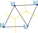 Image Added Image Added
Variant 1: Volume at faces: | Code Block |
|---|
dimensions:
nMesh2_node = 4 ; // nNodes
nMesh2_edge = 5 ; // nEdges
nMesh2_face = 2 ; // nFaces
nMesh2_face_links = 1 ; // nFacePairs
Two = 2 ;
      Three = 3 ;

variables:
// Mesh topology
integer Mesh2 ;
// as in 2D triangular mesh example
integer Mesh2_face_nodes(nMesh2_face, Three) ;
|
Mesh3_face_contour_y:units="m";
// as in 2D triangular mesh example
integer |
Mesh3facecontour_y:long_name = "List of y-points that form outline of flow volume" ;
nodes(nMesh2_edge, Two) ;
// as in |
double Mesh3_edge_x(nMesh3_edge) ; 2D triangular mesh example
// Optional mesh topology variables
integer Mesh2_face_edges(nMesh2_face, Three) ;
|
Mesh3_edge_x:standard_name="projection_x_coordinate";
// as in 2D triangular mesh example
|
Mesh3_edge_x:long_name="Centercoordinateof edges (velocity point)." ;
integer Mesh2_face_links(nMesh2_face_links, Two) ;
// as |
Mesh3_edge_x:units = "m" ; in 2D triangular mesh example
// Mesh node coordinates
double |
Mesh3edgeynMesh3edge
Mesh3_edge_y:standard_name = "projection_y_coordinate" ; as in 2D triangular mesh example
|
Mesh3_edge_y:long_name = "Center coordinate of edges (velocity point)." ;
double Mesh2_node_y(nMesh2_node) ;
                // as in 2D triangular mesh example

// |
Mesh3_edge_y:units = "m" ; Optional mesh face and edge coordinate variables
|
integerMesh3edgenodesnMesh3_edge, Two Mesh3edgenodeslonglink between two nodes integerMesh3_face_nodes(nMesh3_face,nMaxMesh3_face_nodes);
Mesh2_face_x:long_name = "Characteristics longitude of 2D mesh triangle (e.g. circumcenter |
Mesh3_face_nodes:long_name = "Mapping from faces to nodes." ;
integerMesh3links(nMesh3_face_links, Two) ; x:units = "degrees_east" ;
|
FlowLink:long_namelink/interface between two flow elements (faces) Mesh3layersMesh3layersMesh3layersocean_sigma_coordinateMesh3layerssigma at layer midpointsCharacteristics latitude of 2D mesh triangle (e.g. circumcenter coordinate)." ;
|
Mesh3layerspositiveup Mesh3_layers:formula_terms="sigma:Mesh3_layerseta:Mesh3_zwl depth: Mesh3_depthMesh2_face_y:bounds = "Mesh2_face_ybnds" ;
double |
Mesh3interfacesMesh3interfacesMesh3interfacesocean_sigma_coordinateMesh3interfacessigma at layer interfacesLongitude bounds of 2D mesh triangle (i.e. corner coordinates)." ;
|
Mesh3interfacespositiveup Mesh3_interfaces:formula_terms = "sigma: Mesh3_interfaces eta: Mesh3_zwl depth: Mesh3_depth" ;
double Mesh2_face_ybnds(nMesh2_face,Three) ;
|
integer Mesh3Mesh2_face_ybnds:standard_name = "latitude" ; |
Mesh3Mesh2_face_ybnds:long_name = " |
Topologydata Mesh3 2D mesh triangle (i.e. corner coordinates)." ;
|
Mesh3:dimensionality2"degrees_north" ;
double Mesh2_edge_x(nMesh2_edge) ;
|
Mesh3:locations="faceedgenode";
// as in 2D triangular mesh example
|
Mesh3:node_coordinates= "Mesh3_node_x Mesh3_node_y" ;
 double Mesh2_edge_y(nMesh2_edge) ;
                // as in 2D triangular mesh example

// Volume and flux data
|
Mesh3:edge_coordinates= "Mesh3_edge_x Mesh3_edge_y" double Mesh2_volumes(nMesh2_face) ;
|
Mesh3edgenodesMesh3_edge_nodesMesh3:face_coordinatesMesh3_face_x Mesh3_face_yMesh3:face_nodesMesh3_face_nodesMesh3:face_connectivityMesh2_volumes:location = " |
Mesh3__linksMesh3:parent_meshMesh2_volumes:coordinates = " |
CombinedMeshMesh2_face_x Mesh2_face_y" ; |
integerCombiMeshedge_meshnCombiMesh_contacts, Two CombiMesh_edgemeshMeshnumberof contact CombiMeshedge_mesh:valid_range0, 2CombiMeshedge_mesh:valid_values0, 1, 2;CombiMeshedge_mesh:flag_meaningsMesh1 Mesh2 Mesh3integerCombiMesh_edge(nCombiMesh_contacts,Two);
Mesh2_fluxes:coordinates = "Mesh2_edge_x Mesh2_edge_y" ;
|
Variant 2: Volume at nodes: CombiMesh_edge:long_name"Edgenumber of contact" ; integer CombinedMesh(nCombinedMesh_contacts, Four)nMesh2_edge = 5 ; // nEdges
nMesh2_face = 2 ; // nFaces
|
CombinedMesh:long_name="Topologydataof CombinedMesh" ;
nMesh2_face_links = 1 ; // nFacePairs
|
CombinedMesh:sub_meshes "Mesh1 Mesh2 Mesh3" ;
CombinedMesh:contact"CombiMesh_edge_mesh CombiMesh_edge" ;
3 ;

variables:
// Mesh topology
|
doubletime(time); time:standard_name = "time" ;
// as in 2D triangular mesh example
        integer Mesh2_face_nodes(nMesh2_face, Three) ;
|
time:units="secondssince1992-08-3100:00:00";
//1Dmeshnodesmaybemergedwithin 2D triangular mesh example
|
faces.Or2Dmeshfacesmaybemasked and omitted in
// solution output. As a result, allow for a map between flow node numbers and basic mesh entities/numbers).
//
// Relation between basic mesh (nodes/edges/faces) and computational mesh (corners/interfaces/cells)
// (For cell center data, nMesh1_cell <= nMesh1_node, nMesh2_cell <= nMesh2_face)
// (In case of identity maps, leave out the location_map, and specify coordinates, grid and location
// directly in attributes of solution variable.)integer Mesh2_edge_nodes(nMesh2_edge, Two) ;
// as in 2D triangular mesh example
// Optional mesh topology variables
integer Mesh2_face_edges(nMesh2_face, Three) ;
// as in 2D triangular mesh example
|
doubleMesh1cellxnMesh1_cellnMesh2_face_links, Two) ;
// as in 2D triangular mesh example
// Mesh node coordinates
|
Mesh1_cell_x:standard_name = "projection_x_coordinate" ; double Mesh2_node_x(nMesh2_node) ;
|
Mesh1celllongflow cell circumcenter x-coordinate Mesh1cellunitsm";
double Mesh1_cell_y(nMesh1_cell) Mesh1cellystandard_nameprojectiony_coordinate Mesh1cellylong_nameflow cell circumcenter y-coordinate Mesh1_cell_y:units = "m" ;
double Mesh2_node_y(nMesh2_node) ;
|
doubleMesh1_flownode(nMesh1_cell)Mesh2_node_y:standard_name = "latitude" ;
|
Mesh1cellnodemapfromflowcellto 1D node Mesh1cellnodegridMesh1Mesh1cellnodelocationbounds = "Mesh2_node_ybnds" ;
|
//locationofflowcellon topological mesh entity.
double Mesh2_node_xbnds(nMesh2_node, nMaxMesh2_bnds) ;
|
double Mesh1_flowlink(nMesh1_interface) Mesh2_node_xbnds:standard_name = "longitude" ;
|
Mesh1cellnode "map from flowlink to 1D mesh edge" ; "List of x-points that form outline of flow volume" ;
|
Mesh1cellnodegridMesh1Mesh1cellnodelocation"edge" ; // location of flow link on topological mesh entity.
9.9692099683868690E36;
double |
Mesh1zwltimenMesh1cell Mesh1zwlsea_surface_height_above_geoidMesh1zwlmMesh1zwl:location_map = "Mesh1_flownodeybnds:long_name = "List of y-points that form outline of flow volume" ;
|
Mesh1zwlcoordinates"Mesh1_cell_x Mesh1_cell_y" ;9.9692099683868690E36;
// Optional mesh face and edge coordinate variables
double |
Mesh1u(time, nMesh1_interface Mesh1_zwl:standard_name = "sea_water_speed" ;
// as in 2D triangular mesh example
double |
Mesh1_u:long_name = "Velocity (along the edge)" ; Mesh2_face_y(nMesh2_face) ;
|
Mesh1_u:units = "ms-1";
 // as in 2D triangular mesh example
double |
Mesh1u:location_map = "Mesh1_flowlink"Mesh1_u:coordinates = "Mesh1_interface_x Mesh1_interface_y" ;
// as in 2D triangular mesh example
double Mesh2_edge_ |
depthnode
as in 2D triangular mesh example

// Volume and flux data
|
Mesh2_depth:standard_name = "sea_floor_depth_below_geoid" double Mesh2_volumes(nMesh2_node) ;
Mesh2_ |
depthunitsmdepthpositivedowndepthgriddepthvolumes:location = "node" ;
Mesh2_ |
depthvolumes:coordinates = "Mesh2_node_x Mesh2_node_y" ;
double Mesh2_ |
zwltime, face zwlstandardsea_surface_height_above_geoid" ;
Mesh2_zwl:units = "mflux along edge" ;
Mesh2_ |
zwlgridMesh2"
Mesh2_zwl:location = "face Mesh2_zwl:coordinates="Mesh2_face_xMesh2_face_y";
doubleucx(time, nMesh2_face) ; fluxes:mesh = "Mesh2"
Mesh2_ |
ucxstandard_nameeastward_sea_water_velocityucx:units = "m s-1" ;
Mesh2_ucx:grid = "Mesh2"
Mesh2_ucx:location = "face" ;
Mesh2_ucx:coordinates = "Mesh2_face_x Mesh2_face_y" ;
double Mesh2_ucy(time, nMesh2_face) ;
Mesh2_ucy:standard_name = "northward_sea_water_velocity" ;
Mesh2_ucy:units = "m s-1" ;
Mesh2_ucy:grid = "Mesh2"
Mesh2_ucy:location = "face" ;
Mesh2_ucy:coordinates = "Mesh2_face_x Mesh2_face_y" ;
double Mesh2_unorm(time, nMesh2_edge) ; fluxes:coordinates = "Mesh2_edge_x Mesh2_edge_y" ;
|
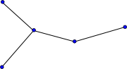
Location index set.Some variables may only be defined at specific locations within the mesh, e.g. only at boundary points or at special locations like weirs and gates. To save space and to improve readability, the concept of a location_index_set is introduced. It is basically identical to the compression option in the the CF-conventions except for the fact that the compression works on a (set of) orthogonal coordinate dimension(s) and the location_index_set works on a topology location. The location index set is an integer variable that contains the indices of the locations at which a specific quantity is defined. The example below defines a location index set "Mesh1_set" as a subset of the "node"s of Mesh1 (red points). The attribute location_index_set of the variable "Mesh_waterlevel" points to this index set and the coordinates attribute points to the corresponding (subset) of latitude and longitude coordinates. The mesh and location attributes of the location_index_set variable are required; the coordinates attribute is optional. Note that the coordinates attributes on both "Mesh1_cell" and "Mesh1_waterlevel" are again redundant since the coordinates could also be obtained by using the index set "Mesh1_set" and the node_coordinates attribute of the "Mesh1" variable. Consistent with all other index variables defined here, the indexing convention of the location index set should be specified using the start_index attribute to the index variable and 0-based indexing is the default. See this section on 0-/1-based indexing for more details. Contrary to a coordinate variable, the index set doesn't have to be monotonic. So, it can be used for creating subsets of the original locations as well as for renumbering the locations. If the location_index_set attribute is used on a variable, then the mesh and location attributes should not also be used on that variable.  Image Added Image Added
Mesh2_unorm:long_name"Normal component of velocity at the interface" ;
Mesh2_unorm:units = "m s-1" ; Mesh2_unorm:grid = "Mesh2"integer Mesh1_set(nMesh1_set) ;
|
Mesh2unormlocationedge Mesh2unormcoordinatesMesh2_edge_x Mesh2_edge_y" ;
todo: meaning?
integer Mesh2_edgetype(nMesh2_edge) ; Defines Mesh1_set as subset of the nodes of Mesh1." ;
|
Mesh2edgetypelong_nameType of edge Mesh2edgetypevalid_range0,2Mesh2edgetypevalidvalues 0,,2;
Mesh1_set:coordinates = "Mesh1_set_x Mesh1_set_y" ;
|
Mesh2_edgetype:flag_meanings = "closed_edge open_internal_edge open_boundary_edge" double Mesh1_set_x(nMesh1_set) ;
|
Mesh2edgetypegridMesh2Mesh2edgetypelocationedgeCharacteristic longitude of set (e.g. longitude of node)." ; |
Mesh2edgetypecoordinatesMesh2_edge_x Mesh2_edge_y
Mesh3depthnMesh3node Mesh3depthsea_floor_depth_below_geoidMesh3depthunitsmCharacteristic latitude of set (e.g. latitude of node)" ;
|
Mesh3depthpositivedown" degrees_north" ;
double Mesh1_waterlevel(time, nMesh1_set) ;
|
Mesh3depthgridMesh3"sea_surface_height_above_geoid" ;
|
Mesh3depthlocationnodeMesh3depth:coordinateswaterlevel:location_index_set = " |
Mesh3_node_x Mesh3_node_y doubleMesh3_zwl(time,nMesh3_face);
Mesh1_waterlevel:coordinates = "Mesh1_set_x |
Mesh3_zwl:standard_name = "sea_surface_height_above_geoid" ;
Mesh3_zwl:units = "m" ;
Mesh3_zwl:grid = "Mesh3"0-/1-based indexingThe indexing using by the CF compression option is 0-based. Therefore, it is most consistent for this CF extension for unstructured data to also use 0-based indexing, which means that points, edges, faces and volumes will be numbered starting with 0. This convention is consistent with languages like C and Java, but unlike FORTRAN and MATLAB. Since many of the unstructured models have been programed in FORTRAN and legacy netCDF files exist that use 1-based indexing (which could be upgraded to be consistent with this new proposal using ncML if 1-based indexing were allowed), we propose to support both 0- and 1-based indexing by means of the start_index attribute. You will find below two examples of the same network geometry using either 0- or 1-based indexing. Switching between 0- and 1-based indexing is as easy as adding 1 to or subtracting 1 from the indices upon reading or writing depending on the setting of start_index; allowing both options should only have a minor impact on the reading routines and no effect at all on the rest of your code. Example of 0-based indexing: 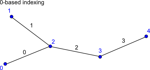 Image Added Image Added
Mesh3_zwl:location"face"
Mesh3_zwl:coordinates"Mesh3_face_x Mesh3_face_y"
double Mesh3_ucx(time, nMesh3_face, nMesh3_layer) ;
// nEdges

        Two = 2;

variables:
// Mesh topology
|
Mesh3_ucx:standard_name = "eastward_sea_water_velocity"Mesh3_ucx:unitsm s-1Mesh3_ucx:gridMesh3"Topology data of 1D network" ;
|
Mesh3_ucx:locationMesh1:topology_dimension = |
"face"Mesh3ucx:Mesh3faceMesh3face Mesh3_layers
doubleMesh3_ucy(time, nMesh3_face, nMesh3_layer) ; Mesh1:edge_node_connectivity = "Mesh1_edge_nodes" ;
|
Mesh3_ucystandardnamenorthward_sea_water_velocityMesh1_edge_x Mesh1_edge_y" ; |
Mesh3_ucy:units = "m s-1"integer Mesh1_edge_nodes(nMesh1_edge, Two) ;
|
Mesh3ucygridMesh3"edge_node_connectivity" ;
|
Mesh3ucylocationface" ;
Maps every edge/link to the two nodes that it connects." ;
|
Mesh3_ucy:coordinates="Mesh3_face_xMesh3_face_yMesh3_layers";
double Mesh3_unorm(time, nMesh3_edge, nMesh3_layer) ; Mesh1_edge_nodes:start_index = 0 ; // default setting, attribute could have been skipped.
// Coordinate variables skipped
data:
Mesh1 = 0 |
Mesh3_unorm:long_name = "Normal component of velocity at the interface" ; ; // dummy
Mesh1_edge_nodes =
0, 2,
|
Mesh3_unorm:units="ms-"; Mesh3_unorm:grid="Mesh3"
Example of 1-based indexing: 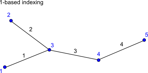 Image Added Image Added
Mesh3_unorm:location"edge"5 ; // nNodes
nMesh1_edge = 4 ; // nEdges
|
Mesh3_unorm:coordinates="Mesh3_edge_xMesh3_edge_yMesh3_layers";TODO meaningMesh3_edgetype(nMesh3_edge) Mesh3_edgetypelongnameType of edge Mesh3_edgetypevalidrange 0, 2 "Topology data of 1D network" ;
|
Mesh3_edgetypevalidvalues 0,,2Mesh3_edgetypeflagmeaningsclosed_edge open_internal_edge open_boundary_edgeMesh1_node_x Mesh1_node_y" ;
|
Mesh3_edgetype:gridMesh1:edge_node_connectivity = " |
Mesh3"Mesh3_edgetype:locationMesh1:edge_coordinates = "Mesh1_edge_x Mesh1_edge_y" ; // optional attribute
integer Mesh1_edge_nodes(nMesh1_edge, Two) ;
|
Mesh3_edgetype:coordinates Mesh1_edge_nodes:cf_role = " |
Mesh3_x Mesh3_edge_y
//globalattributes:
Mesh1_edge_nodes:long_name = "Maps every edge/link to the two nodes |
:institution="Deltares :referencesMesh1_edge_nodes:start_index = |
"http:www.deltares.nl" ; Coordinate variables skipped
data:
Mesh1 |
:source "UNSTRUC"0 ; // dummy
Mesh1_edge_nodes =
|
:history= "Created on 2010-04-12BertJagers\n""2010-06-01, distinguishbasicmesh/netandflowmeshinclude mapping between the two, Arthur van Dam" ;
:Conventions = "CF-1.4:Deltares-0.1" ; |