Introduction & summary
In this tool (wave penetration) you can compute wave penetration patterns travelling into a harbour basin.
The tool requires a shoreline and 2 breakwaters attached to shore (you can inspect the generic data availability in the top panel of the tool).
Optionally, any generic wave data can also be used, in order to fill the wave condition fields.
Wave penetration can be calculated in two ways, depending on the user preference. Using an analytic method, in which wave penatration is computed on a grid within the harbour basin and is based on Cornu spiral waves propagating into the harbour basin. Note that this does not take into account processes such as reflection and diffraction. Besides, also a numerical method can be selected, which uses the Diffrac2DH schemisation to find the penetration patterns of waves entering the harbour basin. This method takes reflection and diffraction into account, though only considers a (single) monochromatic wave. Results of wave penetration should however be interpreted with a considerable range of uncertainty.
How to use the tool
- Open a new project.
- Start in Generic Data by defining a Coastline, two breakwater structures (which enclose the harbour basin) and a wave climate and/or extreme waves (optional). Make sure that the coastline and the breakwaters intersect.
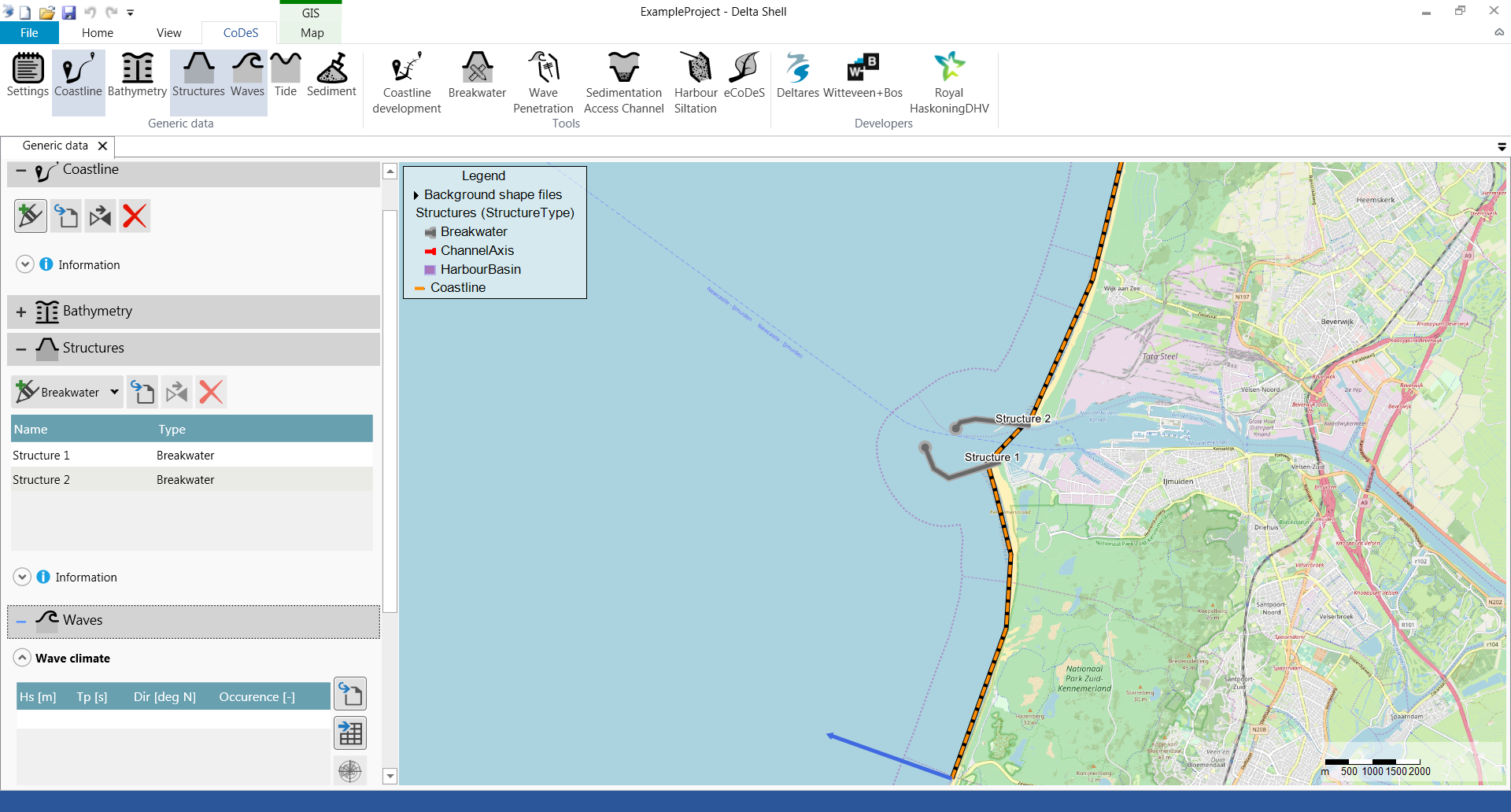
- Open the Wave Penetration tool.
- Provide input according to the user input field description below.

- Press the play button to start the wave penetration calculation.
- After the calculation is finished, the map is shown with a spatial varying field containing the significant waveheight (in meters) within the harbor basins. The following figures show the difference between using the Analytical (left panel) and Diffrac2DH (right panel) method.


- Press the delete button to delete the output from the map.
User input fields
Wave condition
Provide the design wave conditions at the haror entrance. By clicking on the (![]() ) button, you can also select the wave climate and/or extreme wave conditions from the generic data.
) button, you can also select the wave climate and/or extreme wave conditions from the generic data.
| Default Value | Unit | Min. | Max. | Brief Description | |
|---|---|---|---|---|---|
| Hs | 0 | m | 0 | 20 | Significant wave height at the harbor entrance. |
| Tp | 0 | s | 0 | 20 | Peak wave period at the harbor entrance. |
| Dir | 0 | deg N | 0 | 360 | Direction of the waves approaching the harbor entrance (Nautical convention). |
| Dir spreak | 30 | deg | - | - | Directional spreading at the harbor entrance. This option is not yet supported. |
Structures
Select the first and second breakwater which enclose the harbor basin. Only a harbor basin comprising of 2 breakwaters is supported.
Harbor
| Default Value | Unit | Min. | Max. | Brief Description | |
|---|---|---|---|---|---|
| Harbor depth | 10 | m | 0.01 | 9999 | Water depth inside the harbor. |
Calculation type
Select which type of calculation will be performed:
- Analytical - Wave penetration is computed on a grid within the harbour basin and is based on the Cornu spiral principle (solving the Sommerfeld equations incl. Fresnel integrals). Note that this does not take into account wave reflection.
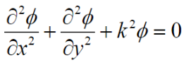
- Diffrac2DH - Wave penetration is computed using the numerical Diffrac2-DH schemisation (solving the Helmholtz equation). This method takes reflection and diffraction into account.
Literature
More information (literature) about the internal workings of the analytical and Diffrac-2DH calculations can be found here:
- Analytical
- Goda, Y., Takayama, T. and Suzuki, Y., “Diffraction diagrams for directional random waves,” Proc. 16th International Conference Coastal Engineering. (Hamburg, 1978) pp. 628-650.
- Carr, J.H. and Stelzriede, M.E. 'Diffraction of Water Waves by Breakwaters' (Section 2.2 in particular)
- M.R., Boshek., "Reflection and Diffraction Around Breakwaters"
- Wolfram MathWorld - Cornu Spiral
- LibreTexts Physics - Cornu's Spiral
- Key equations:
- Fresnel integrals:

- Fresnel integrals:
- Diffrac-2DH
- Diffrac User-Manual (Appendix C in particular)
- Key equations:
- Helmholtz equation:
- Horizontal boundary condition equation:

- Helmholtz equation:
Tool limitations
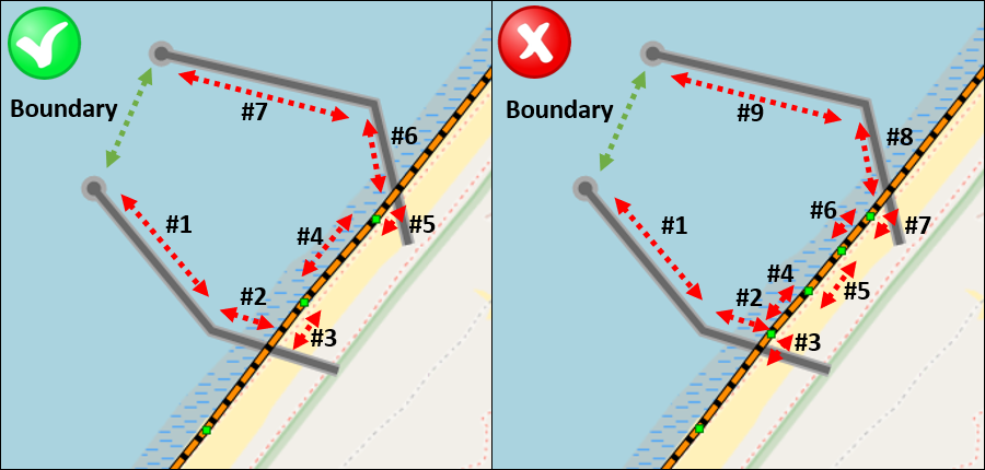
Diffrac-2DH can only handle a maximum of eight (8) reflective boundaries. This means that the number of structure and coastline points should not result in more than eight reflective boundaries in total (excl. open boundary).
In the image below, this concept is visually shown, in the left panel, a total of 7 reflective boundaries are defined (which is ok), in the right panel, a total of 9 reflective boundaries are defined (this is too much).
For the situation in the right panel, only the analytical formation can be used (or the number of coastline points in between breakwaters reduced).
The following processes are not included in the tool: wave directional spreading, bed level changes throughout the harbor, wave reflection (in case of using the analytical method) or varying reflection values (in case of Diffrac-2DH), etc.
More information on the limitations can be found through the provided literature.
Results of the wave penetration tool should therefore be interpreted with a considerable range of uncertainty.
Example cases
The following files (.dsproject) can be downloaded and loaded into CoDeS to serve as examples. They are not based on actual projects, but are intended as illustration.
Unzip the files to an convient folder (but make sure the file structure does not change), and open the .dsproject file from within CoDeS.