...
Most Delft-FEWS systems nowadays use the topology.xml to configure the work process of the forecaster in the IFD-environment. The topology.xml is a mandatory configuration file when you are setting up an IFD-environment (Interactive Forecasting Display). The topology.xml is used to configure the behavior of the forecast panel. This will be explained in more detail in the next sections.

Running workflows from the topology tree
The topology tree can be configured in the following way. The example below shows a simple topology tree with two leaf nodes A and B.
TopologyGroup.xml
It is possible to split the configuration of the topology in separate configuration files.
The main configuration file is always the topology.xml. The other (supporting) configuration files are the topology group files. The topology group files should be placed in the RegionConfigfiles folder. The name of a topology group file should start with TopologyGroup.
An example of a topology group file is shown belowBoth of them belong the group node C.
| Code Block | ||
|---|---|---|
| ||
<?xml version="1.0" encoding="UTFutf-8"?> <topology<topologyGroup xmlns="http://www.wldelft.nl/fews" xmlns:xsi="http://www.w3.org/2001/XMLSchema-instance" xsi:schemaLocation="http://www.wldelft.nl/fews https://fewsdocs.deltares.nl/schemas/version1.0/topologytopologyGroup.xsd"> <nodes<group id="C" name="C">ForecastGroup_Bear"> <node<nodes id="ABear" name="A"/> Bear"> <workflowId>Bear_Forecast</workflowId> <node id="BMergeMAPBear" name="B"/> MergeMAP and Outflow"> <workflowId>Bear_Forecast</workflowId> <moduleInstanceId>SetTimes_Forecast</moduleInstanceId> <moduleInstanceId>MergeMAP_Bear_Forecast</moduleInstanceId> <moduleInstanceId>Merge_RiverWare_Observed_QT</moduleInstanceId> <visibleModifierGroup>None</visibleModifierGroup> </node> </nodes> </topology>group> </topologyGroup> |
The defined topology groups can be used in the topology.xml by using the element <groupId>. An example is shown belowIt is possible to run workflows from the topology panel. In the example below some of the node(s) have a workflow configured.
| Code Block | ||
|---|---|---|
| ||
<?xml<nodes versionid="1.0InflowForecast" encodingname="UTF-8"?Inflow Forecast"> <warmState unit="day" multiplier="11"/> <groupId>ForecastGroup_Bear</groupId> |
Running workflows from the topology tree
The topology tree can be configured in the following way. The example below shows a simple topology tree with two leaf nodes A and B.
Both of them belong the group node C.
| Code Block | ||
|---|---|---|
| ||
<?xml version="1.0" encoding="UTF-8"?> <topology xmlns<topology xmlns="http://www.wldelft.nl/fews" xmlns:xsi="http://www.w3.org/2001/XMLSchema-instance" xsi:schemaLocation="http://www.wldelft.nl/fews https" xmlns:xsi="http://fewsdocswww.deltaresw3.nlorg/schemas/version1.2001/XMLSchema-instance" xsi:schemaLocation="http://www.wldelft.nl/fews https://fewsdocs.deltares.nl/schemas/version1.0/topology.xsd"> <nodes id="C" name="C"> <workflowId>workflowC</workflowId> <node id="A" name="A"/> <workflowId>workflowA</workflowId> </node> <node id="B" name="B"/> </nodes> </topology> |
IFD runs
By default all the workflows started from a leaf node are started in IFD mode. The results of an IFD-run are only temporary available in FEWS (until the next restart) and are only available and visible at the operator client which started the run.
IFD runs are typically used to evaluate the effect of modifiers on the results of a forecast.
Server run
A workflow which is started from a group node will by default be started as a server run. A server run will run at a FSS when it is started from an operator client. When it is started from a stand alone it will run locally but the results of the run will be available after a restart of the system.
It is possible to change these default settings by using the element localRun.
In the example below the runs from leaf nodes A (localRun=false) and B (defaults to false) will run in server mode and the runs started from the group node C will run in IFD mode (localRun=true).
It is possible to run workflows from the topology panel. In the example below some of the node(s) have a workflow configured.
| Code Block | ||
|---|---|---|
| ||
<?xml version="1.0" encoding="UTF-8"?>
<topology xmlns="http://www.wldelft.nl/fews" xmlns:xsi="http://www.w3.org/2001/XMLSchema-instance" xsi:schemaLocation="http:// | ||
| Code Block | ||
| ||
<?xml version="1.0" encoding="UTF-8"?> <topology xmlns="http://www.wldelft.nl/fews" xmlns:xsi="http https://wwwfewsdocs.w3deltares.org/2001/XMLSchema-instance" xsi:schemaLocation="http://www.wldelft.nl/fews https://fewsdocs.deltares.nl/schemas/version1.0/topology.xsd"> <nodes id="nl/schemas/version1.0/topology.xsd"> <nodes id="C" name="C"> <workflowId>workflowC</workflowId> <localRun>true</localRun> <node id="A" name="A"> <workflowId>workflowA</workflowId> <localRun>false</localRun> </node> <node id="B" name="B"/> </nodes>nfonodes> </topology> |
It is possible to connect nodes in the topology. In the example below the node STKA2 is connected to two previous nodes (SBFQ2 and ISKQ2).
| Code Block | ||
|---|---|---|
| ||
<node id="STKA2" name="STKA2 Stikine R Wrangell">
		<previousNodeId>SBFQ2</previousNodeId>
		<previousNodeId>ISKQ2</previousNodeId>
		<workflowId>STKA2_Forecast</workflowId>
</node> |
The way nodes are connected plays an important role when running workflows in IFD mode.
The example below shows the situation before the forecaster starts an IFD run for the node STKA2. The topology tree shows that this node has not run yet (icon is a black dot) and that it is connected to two previous nodes SBFQ2 and ISKQ2.

When the forecaster starts an IFD run for node STKA2 Delft-FEWS will detect that node STKA2 is connected to two other nodes which have to run before the run for STKA2 can be started.
One of these nodes (SBFQ2) also has a previous node which has to run prior to running this node. Before running node STKA2 the IFD system will make sure that first all the necessary previous nodes are run in the correct order before node STKA2 will be run. The example below shows the forecast tree after the run for STKA2 was finished. It shows that not only an IFD run was started for STKA2 but also for all its previous nodes.
By default the workflow on a leaf node is started automatically after selecting the node. This can be disabled by setting the option <enableAutoRun> to false.
The option will apply to all nodes.
For IFD runs the connected previous nodes are always started before the IFD run for the selected node can be run.
For server runs the connected previous nodes are by default not taken into account. If the option <enableRunUpstreamServerNodes> is set to true the previous nodes will also be started prior to running the workflow of the selected node.
The option <checkStatusPreviousServerRun> can be used to force that a server run can only be started if the status of all of its previous nodes is fully successful.
Previous nodes which are connected to a node but belong to a different group in the topology tree are ignored by default when starting previous nodes for a selected node. By setting the option <enableCrossGroupNodeReferencing> to true previous nodes in a different group will also be taken into account.
Please note, if the same workflow node is selected more than once, and a description is specified, then a notification dialog pops up after the OK button is clicked. If the user chooses to change the description, then the edit run options dialog comes back, and the description text would be selected (which indicates the description text is ready to be edited).


Secondary workflow
It is possible to define a secondary workflow for a node. This secondary workflow can be run by clicking the button  in the button bar.
Only the primary workflow determines which icon is shown in the forecast tree.
Below is an example of a node with a secondary workflow.
| Code Block | ||
|---|---|---|
| ||
	<node id="Copy_User_Input_series_ST_Planning_to_RT" name="Copy ST_Planning User Input series">
				<workflowId>Copy_User_Input_series_ST_Planning_to_RT</workflowId>
				<secondaryWorkflowId>Copy_User_Input_series_ST_Planning_to_RT</secondaryWorkflowId>
				<runSecondaryWorkflowAtServer>false</runSecondaryWorkflowAtServer>
				<timeSeriesButtonsPanelId>Observed</timeSeriesButtonsPanelId>
				<graceTime unit="hour" multiplier="1"/>
				<localRun>true</localRun>
				<saveLocalRunEnabled>true</saveLocalRunEnabled>
				<showRunApprovedForecastButton>true</showRunApprovedForecastButton>
</node> |
runSecondaryWorkflowWithTaskRunPropertiesFromIFD
The secondary workflow runs by default with the settings in the xml-file. Since the 2019.02 release however it is also possible to run the secondary workflow with the settings from the IFD.
To enable this the tag runSecondaryWorkflowWithTaskRunPropertiesFromIFD must be set to true.
popupMessageServerRun
With this option it is possible to define a message which will be shown when a server run is started from this node.
Run options panel
It is possible to manually select the task properties which will be used in the runs started from the IFD. This can be done in the panel below the forecast tree. The picture belows shows an example of this panel.
The options which are shown in this panel are configurable. Each node or group of nodes in the topology can have different options.
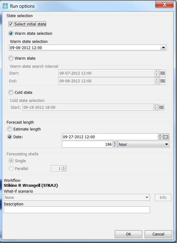
More advanced options are available in the run options panel. This panel is started when the forecaster clicks on the edit run options button.
The "edit run options" button can be disabled by setting the option <disableAdvancedButton> to true. The "edit run options" button can be disabled for a single node or a group node and its children.
In the section below several typical configuration examples are given which will be explained in detail.
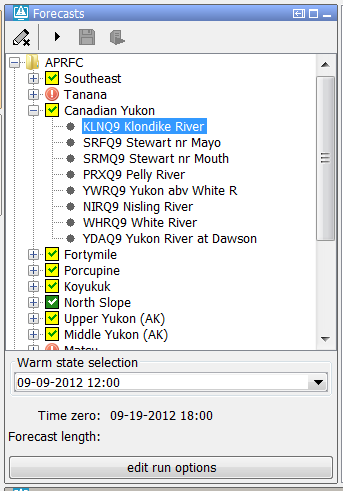
Warm state selection
In a lot of systems, for example NWS systems, only the state selection is configured. The time zero will in this case be equal to the system time.
The forecast length will be determined by the forecast length estimator.
| Code Block | ||
|---|---|---|
| ||
<nodes id="APRFC">
		<showModifiers>true</showModifiers>
		<workflowId>APRFC_Forecast</workflowId>
		<warmState unit="day" multiplier="10"/>
		<!-- Topology added for forecast group Southeast -->
		<nodes id="Southeast" name="Southeast">
<workflowId>Southeast_Forecast</workflowId> |
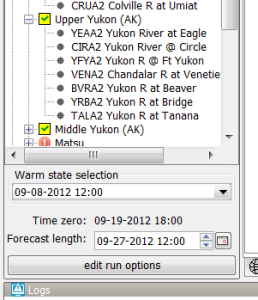
Below a screenshot of the system prior to running a node. The state selection is set to -10 days. The forecast length is not set and the time zero is equal to the system time.
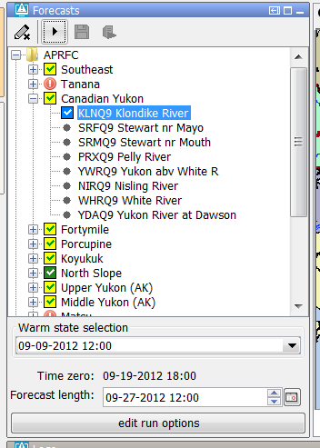
After the run the forecast length which was determined by the forecast length estimator in the run is shown in the panel.
The forecaster can adjust the forecast length by using the time chooser.
It is possible to disable the possiblity to edit the forecast length by using the option <useForecastLengthFromInteractiveForecastDisplay>.
An configuration example is shown below.
| Code Block | ||
|---|---|---|
| ||
<node id="SRYA2" name="SRYA2 Situk R nr Yakutat">
			<workflowId>SRYA2_Forecast</workflowId>
			<useForecastLengthFromInteractiveForecastDisplay>false</useForecastLengthFromInteractiveForecastDisplay>
</node> |
When the system time changes the selected state will also change so the relative time compared to time zero will stay the same.
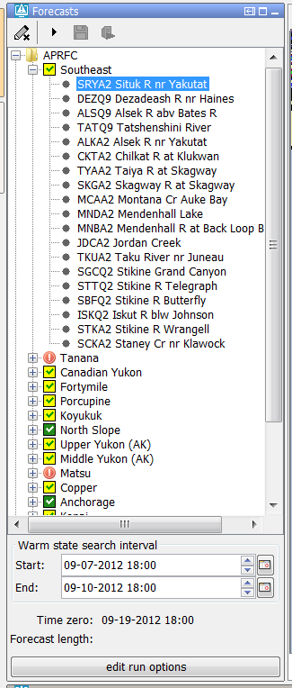
Warm state selection period
The option warm state selection period can be used to set the state selection to a period (relative to the system time) in which the system will search for a warm state.
An example of a node which is configured with a warm state search period is given below.
A configuration example is given below.
| Code Block | ||
|---|---|---|
| ||
<nodes id="Southeast" name="Southeast">
	<workflowId>Southeast_Forecast</workflowId>
	<warmStateSelectionPeriod unit="day" start="-12" end="-9"/>
	<node id="SRYA2" name="SRYA2 Situk R nr Yakutat">
		<workflowId>SRYA2_Forecast</workflowId>
		<useForecastLengthFromInteractiveForecastDisplay>false</useForecastLengthFromInteractiveForecastDisplay>
</node> |
Cold state selection
It is also possible to set the default state selection for a node or a group of nodes to a cold state selection.
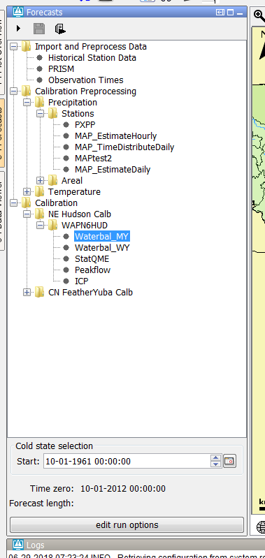
An configuration example is given below.
| Code Block | ||
|---|---|---|
| ||
	<nodes id="WAPN6HUD_calb" name="WAPN6HUD">
				<workflowId>WAPN6HUD_Stats_Calibration</workflowId>
				<coldState unit="day" multiplier="18628"/>
<node id="WAPN6HUD_Waterbalance_Multi-year" name="Waterbal_MY"> |
Fix cold state selection
With the fixedColdState option, the cold state can be fixed to a selected dateTime by the user in the GUI by selecting the checkbox "Keep cold state at current selection". This fixed coldState is inherited by the downstream nodes.
Note: When a user selects the option to fix a cold state to a certain date/time then this will only impact the local client. Only when the user starts a server run for this node the changes (modifiers) will be send to the server and impact the other users.


To enable this option, you need to configure a few files (config examples are give below):
- Topology.xml
- <fixedColdState>, which defines the location attribute modifier in FEWS to store the selected cold state:
- locationId: location the modifiers will be made.
- modifierTypeId: refers to modifier type id as defined in ModifierTypes.xml
- fixedColdStateLocationAttributeId: attribute in which the selected cold state dateTime is stored. This is a date/time attribute.
- fixedcoldStateGroupLocationAttributeId: attribute in which the cold state group is stored. This is a text attribute.
- <workflowId>, which should refer to a workflow including the lcoationId mentioned above
- <fixedColdState>, which defines the location attribute modifier in FEWS to store the selected cold state:
- ModifierTypes.xml
- <locationAttributeModifier> to define the modifierTypeId as referenced in the Topology
- <modifiersGroup> (optional) if you make use of modifiersGroup make sure to list the locationAttributeModifier id here as well
- LocationSets.xml
- <attribute> to add both cold state attributes to the relevant locations
- <dateTimePattern> to define the format of the dateTime attribute
- basins.csv
- add column to create (empty) attributes as defined in locationSets.xml
Note: the location for which the fixedColdState is configured needs to be part of the workflow which is connected to that topology node.
| Code Block | ||||
|---|---|---|---|---|
| ||||
			<node id="coldRelativeStateStartTimeNode">
				<workflowId>workflow2</workflowId>
				<coldState unit="hour" multiplier="6"/>
 				<fixedColdState>
					<locationId>basinA</locationId>
					<modifierTypeId>coldStateModifier</modifierTypeId>
					<fixedColdStateLocationAttributeId>coldStateDateTime</fixedColdStateLocationAttributeId>
					<fixedColdStateGroupLocationAttributeId>coldStateGroup</fixedColdStateGroupLocationAttributeId>
				</fixedColdState>
</node> |
| Code Block | ||||
|---|---|---|---|---|
| ||||
	<attributeModifiers>
		<locationAttributeModifier id="coldStateModifier" name="fixed cold state">
			<modifiableGroup name="coldStateModifiableGroup">
				<locationSetId>basins</locationSetId>
				<attribute id="coldStateDateTime"></attribute>
  				<attribute id="coldStateGroup"></attribute>
		    </modifiableGroup>
		</locationAttributeModifier>
	</attributeModifiers>
|
| Code Block | ||
|---|---|---|
| ||
<locationSet id="basins">
		<csvFile>
			<file>basins.csv</file>
			<geoDatum>WGS 1984</geoDatum>
			<id>%BASIN%</id>
			<name>%SHORT_NAME%</name>
			<dateTimePattern>yyyy-mm-dd HH:mm</dateTimePattern>
			<x>0</x>
			<y>0</y>
			<z>0</z>
			<attribute id="coldStateDatetime">
				<dateTime>%coldStateDatetime%</dateTime>
			</attribute>
			<attribute id="coldStateGroup">
				<text>%coldStateGroup%</text>
			</attribute>
		</csvFile>
</locationSet> |
| Code Block | ||
|---|---|---|
| ||
BASIN, SHORT_NAME, coldStateDatetime, coldStateGroup
basinA, basinA, ,
basinB, basinB, , |
coldStateStartTime
Alternatively, a fixed coldStateStartTime (available since 2019.02) can be configured. This dateTime is hardcoded in the xml, and can not be changed by the user.
| Code Block | ||
|---|---|---|
| ||
	<nodes id="WAPN6HUD_calb" name="WAPN6HUD">
				<workflowId>WAPN6HUD_Stats_Calibration</workflowId>
				<coldStateStartTime date="2019-01-01" />
<node id="WAPN6HUD_Waterbalance_Multi-year" name="Waterbal_MY"> |
No initial state
The option <noInitialState> can be used to disable the state selection for a node so that the state will be selected by the workflow.
An example of a node which has this option enabled is shown below.
A configuration example is given below.
| Code Block | ||
|---|---|---|
| ||
<nodes id="Southeast" name="Southeast">
	<workflowId>Southeast_Forecast</workflowId>
<noInitialState></noInitialState> |
Relative period panel
When the forecaster wants to run a workflow for a certain period of time then the relative period panel is a good option to use. The picture belows shows an example of the relative period panel.

This option is used, for example, in the HERMES-system. Below a configuration example:
| Code Block | ||
|---|---|---|
| ||
<node id="ProcessTest" name="Process Data">
	<workflowId>ProcessImports</workflowId>
	<relativePeriod unit="day" start="-30" end="0"/>
	<localRun>false</localRun>
</node> |
When the system time is changed then the start time and end time will also change so that the relative period will stay the same for a topology node.
It is possible to force the initial start time and end time to match a certain time step. This can be done by using the options <initialStartTimeCardinalTimeStep> and <initialEndTimeCardinalTimeStep>.
To force user edits to the start and/or end time to a certain time step the options <cardinalTimeStepStartTime> and <cardinalTimeStepEndTime> can be used.
If the option <initialStartTimeCardinalTimeStep> is used then the start time will not change when the system time changes. The same applies for the end time and the option <initialEndTimeCardinalTimeStep>.
A configuration example is shown below.
| Code Block | ||
|---|---|---|
| ||
<node id="Process" name="Process Data">
	<previousNodeId>Import</previousNodeId>
	<workflowId>ProcessImports</workflowId>
	<relativePeriod unit="day" start="-10" end="-5"/>
	<cardinalTimeStepStartTime unit="hour" multiplier="6"/>
	<initialStartTimeCardinalTimeStep unit="hour"/>
	<cardinalTimeStepEndTime unit="hour" multiplier="6"/>
	<initialEndTimeCardinalTimeStep unit="hour"/>
	<localRun>false</localRun>
</node> |
Relative period panel with only a start time
It is possible to a create a relative period panel in which the end time is hidden.
Below an example of such a panel.

This panel can be configured in the following way.
| Code Block | ||
|---|---|---|
| ||
<node id="ProcessTest" name="Process Data">
            <workflowId>ProcessImports</workflowId>
            <relativeStartTime unit="day" value="-10"/>
            <localRun>false</localRun>
</node> |
Cold state from current run
To set the state selection at a node to the cold state selection which was used in another run the option <coldStateFromCurrentRun> can be used.
Below a configuration example
| Code Block | ||
|---|---|---|
| ||
<node id="rainfallpolicy_tweed" name="Set Rainfall Policy">
	<workflowId>Tweed_Rainfall_Forecast</workflowId>
	<coldStateFromCurrentRun>
		<workflowId>Tweed_URBS_IFD_Forecast</workflowId>
		<coldState unit="day" multiplier="2"/>
	</coldStateFromCurrentRun>
	<defaultModifierId>Rainfall Policy</defaultModifierId>
	<visibleModifierGroup>URBS_Official_Rainfall</visibleModifierGroup>
	<localRun>true</localRun>
	<showRunApprovedForecastButton>false</showRunApprovedForecastButton>
</node> |
In the example above the cold state which was used in the current run from workflow "Tweed URBS IFD forecast" will be used.
It is possible to define a default state selection for the cases that a current run is not available yet. In the example above this default is set to a cold state selection of 2 days before time zero.
If time zero changes the cold state selection should also change to keep the relative period the same.
Forecast length
To set the forecast length at a fixed length the option <forecastLength> can be used.
It is possible to force the end time of the forecast (time zero plus forecast length) to match a certain time step by using the option <initialForecastLengthCardinalTimeStep>.
The end time of a node is only forced to match this time step when the user selects the node for the first time.
To force the end time of a node to match a certain time step when the forecaster tries the edit the default forecast length the option <cardinalTimeStepForecastLength> can be used.
By default the end time of a node changes when the system time changes so that the forecast length stays the same.
However if for a node the option <initialForecastLengthCardinalTimeStep> is configured then the end time of the node stays the same if the time zero changes.
A configuration example of a node for which a forecast length, an <initialForecastLengthCardinalTimeStep> and a <cardinalTimeStepForecastLength> is configured is shown below.
| Code Block | ||
|---|---|---|
| ||
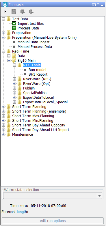
				<node id="B10_Main_RTC" name="Run model">
					<workflowId>Big10_RTCTools_RT</workflowId>
					<forecastLength unit="hour" multiplier="24"/>
					<cardinalTimeStepForecastLength unit="hour"/>
					<initialForecastLengthCardinalTimeStep unit="hour" multiplier="6"/>
					<displayGroupId>Main_RT-RTC</displayGroupId>
					<timeSeriesButtonsPanelId>RT_buttons_Main</timeSeriesButtonsPanelId>
					<viewPermission>execute</viewPermission>
					<visibleModifierGroup>RT</visibleModifierGroup>
					<graceTime unit="hour" multiplier="1"/>
					<localRun>true</localRun>
					<saveLocalRunEnabled>true</saveLocalRunEnabled>
					<showRunApprovedForecastButton>true</showRunApprovedForecastButton>
</node> |
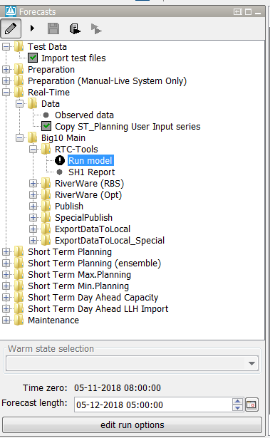
Below a screenshot of this node after it is selected for the first time is shown.

The end time of the run (forecast length) was first set to time zero plus 24 hours. Because this time wasn't a valid time for the configured
<initialForecastLengthCardinalTimeStep> the end time was set to first valid time prior to the end time.
Below a screenshot of the same node after the sytem time was changed. The time zero is changed but the end time of the node is still fixed at the same time.
Time zero
By default the time zero of a node is equal to the system time and not editable.
It is possible to make the time zero editable and to set it to a fixed date/time.
localRun
Workflows started from a leaf node are by default started in IFD mode (i.e. local run). The results of an IFD-run are only temporary available in FEWS (until the next restart) and are only available and visible at the operator client which started the run. IFD runs are typically used to evaluate the effect of modifiers on the results of a forecast.
Workflows started from a group node (nodes) are by default started as a server run. A server run will run at a FSS when it is started from an operator client. When it is started from a stand alone it will run locally but the results of the run will be available after a restart of the system.
You can change these default settings with the element <localRun>. In the example below the runs from leaf nodes A (localRun=false) and B (defaults to false) will run in server mode and the runs started from the group node C will run in IFD mode (localRun=true).
| Code Block | ||
|---|---|---|
| ||
<?xml version="1.0" encoding="UTF-8"?>
<topology xmlns="http://www.wldelft.nl/fews" xmlns:xsi="http://www.w3.org/2001/XMLSchema-instance" xsi:schemaLocation="http://www.wldelft.nl/fews https://fewsdocs.deltares.nl/schemas/version1.0/topology.xsd">
	<nodes id="C" name="C">
		<workflowId>workflowC</workflowId>
		<localRun>true</localRun>
		<node id="A" name="A">
			<workflowId>workflowA</workflowId>
			<localRun>false</localRun>
		</node>
		<node id="B" name="B"/>
	</nodes>nfo
</topology>
|
previousNodeId
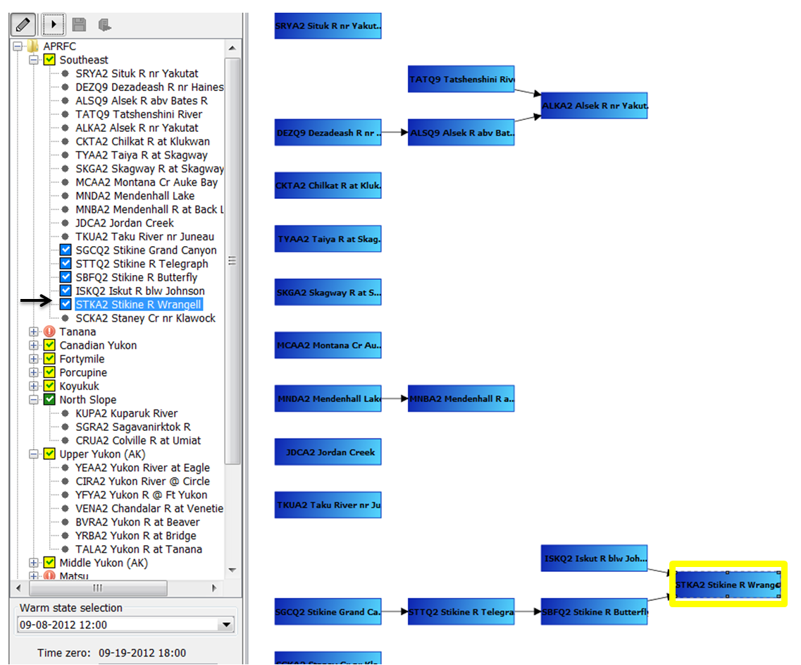
It is possible to connect nodes in the topology. In the example below the node STKA2 is connected to two previous nodes (SBFQ2 and ISKQ2). The way nodes are connected plays an important role when running workflows in IFD mode.
| Code Block | ||
|---|---|---|
| ||
<node id="STKA2" name="STKA2 Stikine R Wrangell">
		<previousNodeId>SBFQ2</previousNodeId>
		<previousNodeId>ISKQ2</previousNodeId>
		<workflowId>STKA2_Forecast</workflowId>
</node> |
Example previousNodeId
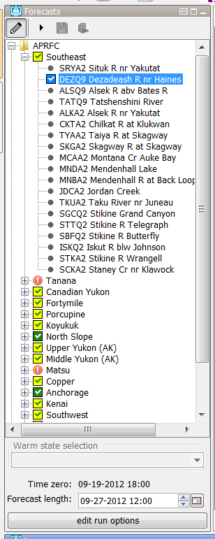
The example below shows the situation before the forecaster starts an IFD run for the node STKA2. The topology tree shows that this node has not run yet (icon is a black dot) and that it is connected to two previous nodes SBFQ2 and ISKQ2.

When the forecaster starts an IFD run for node STKA2 (see arrow) Delft-FEWS will detect that node STKA2 is connected to two other nodes which have to run before the run for STKA2 can be started. One of these nodes (SBFQ2) also has a previous node which has to run prior to running this node. Before running node STKA2 the IFD system will make sure that first all the necessary previous nodes are run in the correct order before node STKA2 will be run.
The screenshot on the right shows the forecast tree after the run for STKA2 was finished. It shows that not only an IFD run was started for STKA2 but also for all its previous nodes.
enableAutoRun
By default the workflow on a leaf node is started automatically after selecting the node. This can be disabled by setting the option <enableAutoRun> to false. The option will apply to all nodes.
enableRunUpstreamServerNodes
For IFD (local) runs the connected previous nodes are always started before the IFD run for the selected node can be run.
For server runs the connected previous nodes are by default not taken into account. If the option <enableRunUpstreamServerNodes> is set to true the previous nodes will also be started prior to running the workflow of the selected node.
checkStatusPreviousServerRun
The option <checkStatusPreviousServerRun> can be used to force that a server run can only be started if the status of all of its previous nodes is fully successful.
enableCrossGroupNodeReferencing
Previous nodes which are connected to a node but belong to a different group in the topology tree are ignored by default when starting previous nodes for a selected node. By setting the option <enableCrossGroupNodeReferencing> to true previous nodes in a different group will also be taken into account.
Note, if the same workflow node is selected more than once, and a description is specified, then a notification dialog pops up after the OK button is clicked. If the user chooses to change the description, then the edit run options dialog comes back, and the description text would be selected (which indicates the description text is ready to be edited).
Secondary workflow
It is possible to define a secondary workflow for a node. This secondary workflow can be run by clicking the button in the button bar.
Only the primary workflow determines which icon is shown in the forecast tree.
Below is an example of a node with a secondary workflow.
| Code Block | ||
|---|---|---|
| ||
	<node id="Copy_User_Input_series_ST_Planning_to_RT" name="Copy ST_Planning User Input series">
				<workflowId>Copy_User_Input_series_ST_Planning_to_RT</workflowId>
				<secondaryWorkflowId>Copy_User_Input_series_ST_Planning_to_RT</secondaryWorkflowId>
				<runSecondaryWorkflowAtServer>false</runSecondaryWorkflowAtServer>
				<timeSeriesButtonsPanelId>Observed</timeSeriesButtonsPanelId>
				<graceTime unit="hour" multiplier="1"/>
				<localRun>true</localRun>
				<saveLocalRunEnabled>true</saveLocalRunEnabled>
				<showRunApprovedForecastButton>true</showRunApprovedForecastButton>
</node> |
runSecondaryWorkflowWithTaskRunPropertiesFromIFD
The secondary workflow runs by default with the settings in the xml-file. Since the 2019.02 release however it is also possible to run the secondary workflow with the settings from the IFD.
To enable this the tag runSecondaryWorkflowWithTaskRunPropertiesFromIFD must be set to true.
popupMessageServerRun
With this option it is possible to define a message which will be shown when a server run is started from this node.
Run options panel
It is possible to manually select the task properties which will be used in the runs started from the IFD. This can be done in the panel below the forecast tree. The picture belows shows an example of this panel.
The options which are shown in this panel are configurable. Each node or group of nodes in the topology can have different options.
More advanced options are available in the run options panel. This panel is started when the forecaster clicks on the edit run options button.
The "edit run options" button can be disabled by setting the option <disableAdvancedButton> to true. The "edit run options" button can be disabled for a single node or a group node and its children.
In the section below several typical configuration examples are given which will be explained in detail.
Warm state selection
In a lot of systems, for example NWS systems, only the state selection is configured. The time zero will in this case be equal to the system time.
The forecast length will be determined by the forecast length estimator.
| Code Block | ||
|---|---|---|
| ||
<nodes id="APRFC">
		<showModifiers>true</showModifiers>
		<workflowId>APRFC_Forecast</workflowId>
		<warmState unit="day" multiplier="10"/>
		<!-- Topology added for forecast group Southeast -->
		<nodes id="Southeast" name="Southeast">
<workflowId>Southeast_Forecast</workflowId> |
Below a screenshot of the system prior to running a node. The state selection is set to -10 days. The forecast length is not set and the time zero is equal to the system time.
After the run the forecast length which was determined by the forecast length estimator in the run is shown in the panel.
The forecaster can adjust the forecast length by using the time chooser.
It is possible to disable the possiblity to edit the forecast length by using the option <useForecastLengthFromInteractiveForecastDisplay>.
An configuration example is shown below.
| Code Block | ||
|---|---|---|
| ||
<node id="SRYA2" name="SRYA2 Situk R nr Yakutat">
			<workflowId>SRYA2_Forecast</workflowId>
			<useForecastLengthFromInteractiveForecastDisplay>false</useForecastLengthFromInteractiveForecastDisplay>
</node> |
When the system time changes the selected state will also change so the relative time compared to time zero will stay the same.
Warm state selection period
The option warm state selection period can be used to set the state selection to a period (relative to the system time) in which the system will search for a warm state.
An example of a node which is configured with a warm state search period is given below.
A configuration example is given below.
| Code Block | ||
|---|---|---|
| ||
<nodes id="Southeast" name="Southeast">
	<workflowId>Southeast_Forecast</workflowId>
	<warmStateSelectionPeriod unit="day" start="-12" end="-9"/>
	<node id="SRYA2" name="SRYA2 Situk R nr Yakutat">
		<workflowId>SRYA2_Forecast</workflowId>
		<useForecastLengthFromInteractiveForecastDisplay>false</useForecastLengthFromInteractiveForecastDisplay>
</node> |
Cold state selection
It is also possible to set the default state selection for a node or a group of nodes to a cold state selection.
An configuration example is given below.
| Code Block | ||
|---|---|---|
| ||
	<nodes id="WAPN6HUD_calb" name="WAPN6HUD">
				<workflowId>WAPN6HUD_Stats_Calibration</workflowId>
				<coldState unit="day" multiplier="18628"/>
<node id="WAPN6HUD_Waterbalance_Multi-year" name="Waterbal_MY"> |
Cold state from current run
To set the state selection at a node to the cold state selection which was used in another run the option <coldStateFromCurrentRun> can be used.
Below a configuration example
| Code Block | ||
|---|---|---|
| ||
<node id="rainfallpolicy_tweed" name="Set Rainfall Policy">
	<workflowId>Tweed_Rainfall_Forecast</workflowId>
	<coldStateFromCurrentRun>
		<workflowId>Tweed_URBS_IFD_Forecast</workflowId>
		<coldState unit="day" multiplier="2"/>
	</coldStateFromCurrentRun>
	<defaultModifierId>Rainfall Policy</defaultModifierId>
	<visibleModifierGroup>URBS_Official_Rainfall</visibleModifierGroup>
	<localRun>true</localRun>
	<showRunApprovedForecastButton>false</showRunApprovedForecastButton>
</node> |
In the example above the cold state which was used in the current run from workflow "Tweed URBS IFD forecast" will be used.
It is possible to define a default state selection for the cases that a current run is not available yet. In the example above this default is set to a cold state selection of 2 days before time zero.
If time zero changes the cold state selection should also change to keep the relative period the same.
Fix cold state selection
With the fixedColdState option, the cold state can be fixed to a selected dateTime by the user in the GUI by selecting the checkbox "Keep cold state at current selection". This fixed coldState is inherited by the downstream nodes.
Note: When a user selects the option to fix a cold state to a certain date/time then this will only impact the local client. Only when the user starts a server run for this node the changes (modifiers) will be send to the server and impact the other users.
To enable this option, you need to configure a few files (config examples are give below):
- Topology.xml
- <fixedColdState>, which defines the location attribute modifier in FEWS to store the selected cold state:
- locationId: location the modifiers will be made.
- modifierTypeId: refers to modifier type id as defined in ModifierTypes.xml
- fixedColdStateLocationAttributeId: attribute in which the selected cold state dateTime is stored. This is a date/time attribute.
- fixedcoldStateGroupLocationAttributeId: attribute in which the cold state group is stored. This is a text attribute.
- <workflowId>, which should refer to a workflow including the lcoationId mentioned above
- <fixedColdState>, which defines the location attribute modifier in FEWS to store the selected cold state:
- ModifierTypes.xml
- <locationAttributeModifier> to define the modifierTypeId as referenced in the Topology
- <modifiersGroup> (optional) if you make use of modifiersGroup make sure to list the locationAttributeModifier id here as well
- LocationSets.xml
- <attribute> to add both cold state attributes to the relevant locations
- <dateTimePattern> to define the format of the dateTime attribute
- basins.csv
- add column to create (empty) attributes as defined in locationSets.xml
Note: the location for which the fixedColdState is configured needs to be part of the workflow which is connected to that topology node.
| Code Block | ||||
|---|---|---|---|---|
| ||||
			<node id="coldRelativeStateStartTimeNode">
				<workflowId>workflow2</workflowId>
				<coldState unit="hour" multiplier="6"/>
 				<fixedColdState>
					<locationId>basinA</locationId>
					<modifierTypeId>coldStateModifier</modifierTypeId>
					<fixedColdStateLocationAttributeId>coldStateDateTime</fixedColdStateLocationAttributeId>
					<fixedColdStateGroupLocationAttributeId>coldStateGroup</fixedColdStateGroupLocationAttributeId>
				</fixedColdState>
</node> |
| Code Block | ||||
|---|---|---|---|---|
| ||||
	<attributeModifiers>
		<locationAttributeModifier id="coldStateModifier" name="fixed cold state">
			<modifiableGroup name="coldStateModifiableGroup">
				<locationSetId>basins</locationSetId>
				<attribute id="coldStateDateTime"></attribute>
  				<attribute id="coldStateGroup"></attribute>
		    </modifiableGroup>
		</locationAttributeModifier>
	</attributeModifiers>
|
| Code Block | ||
|---|---|---|
| ||
<locationSet id="basins">
		<csvFile>
			<file>basins.csv</file>
			<geoDatum>WGS 1984</geoDatum>
			<id>%BASIN%</id>
			<name>%SHORT_NAME%</name>
			<dateTimePattern>yyyy-mm-dd HH:mm</dateTimePattern>
			<x>0</x>
			<y>0</y>
			<z>0</z>
			<attribute id="coldStateDatetime">
				<dateTime>%coldStateDatetime%</dateTime>
			</attribute>
			<attribute id="coldStateGroup">
				<text>%coldStateGroup%</text>
			</attribute>
		</csvFile>
</locationSet> |
| Code Block | ||
|---|---|---|
| ||
BASIN, SHORT_NAME, coldStateDatetime, coldStateGroup
basinA, basinA, ,
basinB, basinB, , |
coldStateStartTime
Alternatively, a fixed coldStateStartTime (available since 2019.02) can be configured. This dateTime is hardcoded in the xml, and can not be changed by the user.
| Code Block | ||
|---|---|---|
| ||
	<nodes id="WAPN6HUD_calb" name="WAPN6HUD">
				<workflowId>WAPN6HUD_Stats_Calibration</workflowId>
				<coldStateStartTime date="2019-01-01" />
<node id="WAPN6HUD_Waterbalance_Multi-year" name="Waterbal_MY"> |
No initial state
The option <noInitialState> can be used to disable the state selection for a node so that the state will be selected by the workflow.
An example of a node which has this option enabled is shown below.
A configuration example is given below.
| Code Block | ||
|---|---|---|
| ||
<nodes id="Southeast" name="Southeast">
	<workflowId>Southeast_Forecast</workflowId>
<noInitialState></noInitialState> |
Relative period panel
When the forecaster wants to run a workflow for a certain period of time then the relative period panel is a good option to use. The picture belows shows an example of the relative period panel.
This option is used, for example, in the HERMES-system. Below a configuration example:
| Code Block | ||
|---|---|---|
| ||
<node id="ProcessTest" name="Process Data">
	<workflowId>ProcessImports</workflowId>
	<relativePeriod unit="day" start="-30" end="0"/>
	<localRun>false</localRun>
</node> |
When the system time is changed then the start time and end time will also change so that the relative period will stay the same for a topology node.
It is possible to force the initial start time and end time to match a certain time step. This can be done by using the options <initialStartTimeCardinalTimeStep> and <initialEndTimeCardinalTimeStep>.
To force user edits to the start and/or end time to a certain time step the options <cardinalTimeStepStartTime> and <cardinalTimeStepEndTime> can be used.
If the option <initialStartTimeCardinalTimeStep> is used then the start time will not change when the system time changes. The same applies for the end time and the option <initialEndTimeCardinalTimeStep>.
A configuration example is shown belowThe code snippet below shows a configuration example.
| Code Block | ||
|---|---|---|
| ||
<node id="ZWF_LHM_Z0_REF2017BP18Process" name="Files LHM zonder zoutProcess Data"> <workflowId>ZWF_LHM_Z0_REF2017BP18<<previousNodeId>Import</previousNodeId> <workflowId>ProcessImports</workflowId> <timeZero date<relativePeriod unit="day" start="2004-01-01" time="00:00:00-10" end="-5"/> <cardinalTimeStepStartTime unit="hour" multiplier="6"/> <localRun>false</localRun> </node><initialStartTimeCardinalTimeStep unit="hour"/> <cardinalTimeStepEndTime unit="hour" multiplier="6"/> <initialEndTimeCardinalTimeStep unit="hour"/> <localRun>false</localRun> </node> |
Relative period panel with only a start time
It is possible to a create a relative period panel in which the end time is hidden.
Below an example of such a panel.
This panel can be configured in the following wayTo make the time zero editable and/or to shfit the time zero compared to the system time the option <timeZeroShift> can be used.
| Code Block | ||
|---|---|---|
| ||
<nodes<node id="WaterOrder HADT1ProcessTest" name="WaterProcess Order ApalachiaData"> <timeZeroShift unit="hour" multiplier="0"/> <node id="WaterOrder_HADT1" name="Adjust Water Order"> <locationId>HADT1</locationId> <workflowId>CalculateSpill_WaterOrder_HADT1</workflowId> |
If the shift is set to 0 then the time zero will be editable but equal to the system time.
Custom info label
It is possible to define a custom info label which be shown (if configured) below the run options.

It is possible to use location attribute in the custom info label. if a value is modified it will be colored blue.
Below a configuration example.
            <workflowId>ProcessImports</workflowId>
            <relativeStartTime unit="day" value="-10"/>
            <localRun>false</localRun>
</node> |
Forecast length
To set the forecast length at a fixed length the option <forecastLength> can be used.
It is possible to force the end time of the forecast (time zero plus forecast length) to match a certain time step by using the option <initialForecastLengthCardinalTimeStep>.
The end time of a node is only forced to match this time step when the user selects the node for the first time.
To force the end time of a node to match a certain time step when the forecaster tries the edit the default forecast length the option <cardinalTimeStepForecastLength> can be used.
By default the end time of a node changes when the system time changes so that the forecast length stays the same.
However if for a node the option <initialForecastLengthCardinalTimeStep> is configured then the end time of the node stays the same if the time zero changes.
A configuration example of a node for which a forecast length, an <initialForecastLengthCardinalTimeStep> and a <cardinalTimeStepForecastLength> is configured is shown below.
| Code Block | ||
|---|---|---|
| ||
<node id="B10_Main_RTC" name="Run model | ||
| Code Block | ||
| ||
<node id="Big10_RUN_Riverware_ST_Planning" name="Riverware (RBS) test"> <workflowId>Big10_RiverWareRTCTools_ST_Planning<RT</workflowId> <displayGroupId>ST_P_Big10_SUM_Riverware</displayGroupId> <forecastLength unit="hour" multiplier="24"/> <timeSeriesButtonsPanelId>ST_BASIN_buttons</timeSeriesButtonsPanelId> <cardinalTimeStepForecastLength unit="hour"/> <customInfoLabel> <initialForecastLengthCardinalTimeStep unit="hour" multiplier="6"/> <labelText>This is an example! first attribute: @wMarketChoice_RT@ second attribute: @SPILL_PRIORITY_RT@</labelText><displayGroupId>Main_RT-RTC</displayGroupId> <timeSeriesButtonsPanelId>RT_buttons_Main</timeSeriesButtonsPanelId> <locationId>BPA<<viewPermission>execute</locationId>viewPermission> <overrulingUnmodifiedDateTimeAttributeValue> <attributeId>wMarketChoice_RT</attributeId><visibleModifierGroup>RT</visibleModifierGroup> <offset<graceTime unit="dayhour" multiplier="1"/> <timeStep unit="day"/> <localRun>true</localRun> <<saveLocalRunEnabled>true</overrulingUnmodifiedDateTimeAttributeValue>saveLocalRunEnabled> </customInfoLabel> <graceTime unit="hour" multiplier="5"/><showRunApprovedForecastButton>true</showRunApprovedForecastButton> <localRun>true</localRun> <saveLocalRunEnabled>true</saveLocalRunEnabled> <showRunApprovedForecastButton>true</showRunApprovedForecastButton> </node> |
It a date/time attribute is not modified the default value will be shown. It is also possible to configure an overruling value if the date/time attribute is unmodfied.
This can be done by using the overrulingUnmodifiedDateTimeAttributeValue. The value can be configured by defining an offset and a time step.
The overruling value will be determined by adding the configured offset to the time zero of the node and setting the determined time to the first valid time of the defined time step.
Custom colors
You can configure the text and background color(selected and non-selected). These are optional fields, you can configure all, none, or some. These properties can be configured on individual nodes and group nodes. Feature available since 2019.02.
</node> |
Below a screenshot of this node after it is selected for the first time is shown.
The end time of the run (forecast length) was first set to time zero plus 24 hours. Because this time wasn't a valid time for the configured
<initialForecastLengthCardinalTimeStep> the end time was set to first valid time prior to the end time.
Below a screenshot of the same node after the sytem time was changed. The time zero is changed but the end time of the node is still fixed at the same time.
Time zero
By default the time zero of a node is equal to the system time and not editable.
It is possible to make the time zero editable and to set it to a fixed date/time.
The code snippet below shows a configuration example.Example:
| Code Block | ||||
|---|---|---|---|---|
| ||||
<?xml version="1.0" encoding="UTF-8"?>
<!-- edited with XMLSpy v2009 sp1 (http://www.altova.com) by ICT (Stichting Deltares) -->
<topology xmlns="http://www.wldelft.nl/fews" xmlns:xsi="http://www.w3.org/2001/XMLSchema-instance"
		  xsi:schemaLocation="http://www.wldelft.nl/fews https://fewsdocs.deltares.nl/schemas/version1.0/topology.xsd">

	<enableAutoRun>false</enableAutoRun>

	<nodes id="Tasks">
		<node id="Import" name="Import">
			<workflowId>Import</workflowId>
			<backgroundSelectionColor>forest green</backgroundSelectionColor>
			<backgroundNonSelectionColor>pale green4</backgroundNonSelectionColor>
		</node>
		<node id="Transformation" name="Transformation">
			<workflowId>Transformation</workflowId>
			<textSelectionColor>gray18</textSelectionColor>
			<textNonSelectionColor>dark salmon</textNonSelectionColor>
		</node>
		<node id="CanadaMeteo" name="CanadaMeteo">
			<workflowId>CanadaMeteo</workflowId>
			<backgroundSelectionColor>light yellow3</backgroundSelectionColor>
			<backgroundNonSelectionColor>turquoise3</backgroundNonSelectionColor>
			<textSelectionColor>yellow</textSelectionColor>
			<textNonSelectionColor>red</textNonSelectionColor>
		</node>
		<node id="NoosImport" name="NoosImport">
			<workflowId>NoosImport</workflowId>
			<textSelectionColor>yellow</textSelectionColor>
			<backgroundNonSelectionColor>light pink2</backgroundNonSelectionColor>
		</node>
		<node id="RotterdamPort" name="RotterdamPort">
			<workflowId>RotterdamPort</workflowId>
			<textNonSelectionColor>peach puff</textNonSelectionColor>
		</node>
		<node id="KiwisImport" name="KiwisImport">
			<workflowId>KiwisImport</workflowId>
		</node>
		<node id="TaoGrid" name="TaoGrid">
			<workflowId>TaoGrid</workflowId>
			<backgroundNonSelectionColor>cornsilk</backgroundNonSelectionColor>
		</node>
		<node id="MunisenseImport" name="MunisenseImport">
			<workflowId>MunisenseImport</workflowId>
		</node>
		<backgroundSelectionColor>light yellow3</backgroundSelectionColor>
		<backgroundNonSelectionColor>turquoise3</backgroundNonSelectionColor>
		<textSelectionColor>yellow</textSelectionColor>
		<textNonSelectionColor>red</textNonSelectionColor>
	</nodes>
</topology> |
Approve forecast automatically
A run started from the IFD is by default automatically approved. Only when the configurator defines in the workflow descriptors that the workflow should not be automatically approved the forecast is not automatically approved.
When the config option enableAutoApprove is used and set to true, an Approve checkbox will appear on the run options panel. With this checkbox the forecaster can determine if the forecast should be approved automatically after the run. When defining enableAutoApprove=false, the default IFD behaviour is followed with the checkbox hidden.
The initial value of the check box is determined by the autoApprove setting of the workflowDescriptor.
Note: the Approve check box will never appear if allowApprove=false in workflowDescriptor. In this case the inconsistency between the autoApprove setting of the topology and the workflowDescriptor is flagged in a Config.Warn.
| Code Block | ||
|---|---|---|
| ||
<nodes id="exampleGroupNode">
   <workflowId>workflowA</workflowId>
   <enableAutoApprove>true</enableAutoApprove>
   <node id="exampleChildNode">
      <workflowId>workflowB</workflowId>
   </node>
</nodes> |
TopologyGroup.xml
It is possible to split the configuration of the topology in separate configuration files.
The main configuration file is always the topology.xml. The other (supporting) configuration files are the topology group files. The topology group files should be placed in the RegionConfigfiles folder. The name of a topology group file should start with TopologyGroup.
An example of a topology group file is shown below.
| Code Block | ||
|---|---|---|
| ||
<?xml version="1.0" encoding="utf-8"?>
<topologyGroup xmlns="http://www.wldelft.nl/fews" xmlns:xsi="http://www.w3.org/2001/XMLSchema-instance" xsi:schemaLocation="http://www.wldelft.nl/fews https://fewsdocs.deltares.nl/schemas/version1.0/topologyGroup.xsd">
	<group id="ForecastGroup_Bear">
		<nodes id="Bear" name="Bear">
			<workflowId>Bear_Forecast</workflowId>
			<node id="MergeMAPBear" name="MergeMAP and Outflow">
				<workflowId>Bear_Forecast</workflowId>
				<moduleInstanceId>SetTimes_Forecast</moduleInstanceId>
				<moduleInstanceId>MergeMAP_Bear_Forecast</moduleInstanceId>
				<moduleInstanceId>Merge_RiverWare_Observed_QT</moduleInstanceId>
				<visibleModifierGroup>None</visibleModifierGroup>
			</node>
		</nodes>
	</group>
</topologyGroup>
|
<node id="ZWF_LHM_Z0_REF2017BP18" name="Files LHM zonder zout">
	<workflowId>ZWF_LHM_Z0_REF2017BP18</workflowId>
	<timeZero date="2004-01-01" time="00:00:00"/>
	<localRun>false</localRun>
</node> |
To make the time zero editable and/or to shfit the time zero compared to the system time the option <timeZeroShift> can be used.
| Code Block | ||
|---|---|---|
| ||
<nodes id="WaterOrder HADT1" name="Water Order Apalachia">
	<timeZeroShift unit="hour" multiplier="0"/>
	<node id="WaterOrder_HADT1" name="Adjust Water Order">
		<locationId>HADT1</locationId>
<workflowId>CalculateSpill_WaterOrder_HADT1</workflowId> |
If the shift is set to 0 then the time zero will be editable but equal to the system time.
Custom info label
It is possible to define a custom info label which be shown (if configured) below the run options.
It is possible to use location attribute in the custom info label. if a value is modified it will be colored blue.
Below a configuration example.
| Code Block | ||
|---|---|---|
| ||
<node id="Big10_RUN_Riverware_ST_Planning" name="Riverware (RBS) test">
				<workflowId>Big10_RiverWare_ST_Planning</workflowId>
				<displayGroupId>ST_P_Big10_SUM_Riverware</displayGroupId>
				<timeSeriesButtonsPanelId>ST_BASIN_buttons</timeSeriesButtonsPanelId>
				<customInfoLabel>
						<labelText>This is an example! first attribute: @wMarketChoice_RT@  second attribute: @SPILL_PRIORITY_RT@</labelText>
						<locationId>BPA</locationId>
						<overrulingUnmodifiedDateTimeAttributeValue>
							<attributeId>wMarketChoice_RT</attributeId>
							<offset unit="day" multiplier="1"/>
							<timeStep unit="day"/>
						</overrulingUnmodifiedDateTimeAttributeValue>
				</customInfoLabel>
				<graceTime unit="hour" multiplier="5"/>
				<localRun>true</localRun>
				<saveLocalRunEnabled>true</saveLocalRunEnabled>
				<showRunApprovedForecastButton>true</showRunApprovedForecastButton>
</node> |
It a date/time attribute is not modified the default value will be shown. It is also possible to configure an overruling value if the date/time attribute is unmodfied.
This can be done by using the overrulingUnmodifiedDateTimeAttributeValue. The value can be configured by defining an offset and a time step.
The overruling value will be determined by adding the configured offset to the time zero of the node and setting the determined time to the first valid time of the defined time step.
Custom colors
You can configure the text and background color(selected and non-selected). These are optional fields, you can configure all, none, or some. These properties can be configured on individual nodes and group nodes. Feature available since 2019.02.
Example:
| Code Block | ||||
|---|---|---|---|---|
| ||||
<?xml version="1.0" encoding="UTF-8"?>
<!-- edited with XMLSpy v2009 sp1 (http://www.altova.com) by ICT (Stichting Deltares) -->
<topology xmlns="http://www.wldelft.nl/fews" xmlns:xsi="http://www.w3.org/2001/XMLSchema-instance"
		  xsi:schemaLocation="http://www.wldelft.nl/fews https://fewsdocs.deltares.nl/schemas/version1.0/topology.xsd">

	<enableAutoRun>false</enableAutoRun>

	<nodes id="Tasks">
		<node id="Import" name="Import">
			<workflowId>Import</workflowId>
			<backgroundSelectionColor>forest green</backgroundSelectionColor>
			<backgroundNonSelectionColor>pale green4</backgroundNonSelectionColor>
		</node>
		<node id="Transformation" name="Transformation">
			<workflowId>Transformation</workflowId>
			<textSelectionColor>gray18</textSelectionColor>
			<textNonSelectionColor>dark salmon</textNonSelectionColor>
		</node>
		<node id="CanadaMeteo" name="CanadaMeteo">
			<workflowId>CanadaMeteo</workflowId>
			<backgroundSelectionColor>light yellow3</backgroundSelectionColor>
			<backgroundNonSelectionColor>turquoise3</backgroundNonSelectionColor>
			<textSelectionColor>yellow</textSelectionColor>
			<textNonSelectionColor>red</textNonSelectionColor>
		</node>
		<node id="NoosImport" name="NoosImport">
			<workflowId>NoosImport</workflowId>
			<textSelectionColor>yellow</textSelectionColor>
			<backgroundNonSelectionColor>light pink2</backgroundNonSelectionColor>
		</node>
		<node id="RotterdamPort" name="RotterdamPort">
			<workflowId>RotterdamPort</workflowId>
			<textNonSelectionColor>peach puff</textNonSelectionColor>
		</node>
		<node id="KiwisImport" name="KiwisImport">
			<workflowId>KiwisImport</workflowId>
		</node>
		<node id="TaoGrid" name="TaoGrid">
			<workflowId>TaoGrid</workflowId>
			<backgroundNonSelectionColor>cornsilk</backgroundNonSelectionColor>
		</node>
		<node id="MunisenseImport" name="MunisenseImport">
			<workflowId>MunisenseImport</workflowId>
		</node>
		<backgroundSelectionColor>light yellow3</backgroundSelectionColor>
		<backgroundNonSelectionColor>turquoise3</backgroundNonSelectionColor>
		<textSelectionColor>yellow</textSelectionColor>
		<textNonSelectionColor>red</textNonSelectionColor>
	</nodes>
</topology> |
Approve forecast automatically
A run started from the IFD is by default automatically approved. Only when the configurator defines in the workflow descriptors that the workflow should not be automatically approved the forecast is not automatically approved.
When the config option enableAutoApprove is used and set to true, an Approve checkbox will appear on the run options panel. With this checkbox the forecaster can determine if the forecast should be approved automatically after the run. When defining enableAutoApprove=false, the default IFD behaviour is followed with the checkbox hidden.
The initial value of the check box is determined by the autoApprove setting of the workflowDescriptor.
Note: the Approve check box will never appear if allowApprove=false in workflowDescriptor. In this case the inconsistency between the autoApprove setting of the topology and the workflowDescriptor is flagged in a Config.WarnThe defined topology groups can be used in the topology.xml by using the element <groupId>. An example is shown below.
| Code Block | ||
|---|---|---|
| ||
<nodes id="InflowForecastexampleGroupNode" name="Inflow Forecast"> <warmState unit="day" multiplier="11"/> <groupId>ForecastGroup_Bear</groupId> > <workflowId>workflowA</workflowId> <enableAutoApprove>true</enableAutoApprove> <node id="exampleChildNode"> <workflowId>workflowB</workflowId> </node> </nodes> |
Interaction with other displays
...
The option <url> can be used to configure an URL for each node. After selecting the node the URL will be displayed automatically in the web browser display.
timeSeriesButtonPanelId
(Since 2014.01) Reference to time series button panel that becomes visible when this topology node is activated. For this functionality you need to configure the time series button panel in Explorer.xml and add 17 TimeSeriesButtonsPanels to the DisplayConfigFiles.
Config examples
Examples from Topology.xml c.q. TopologyGroup.xml are shown below.
...
| Code Block | ||
|---|---|---|
| ||
<nodes id="SSD_NL" name="SSD NL"> <node id="Overview_WMCN" name="Overview Nederland"> <mainPanel>schematic status display</mainPanel> <scadaDisplayId>ScadaOverview_WMCN</scadaDisplayId> <scadaPanelId>Overview_WMCN</scadaPanelId> </node> <node id="Forecast_WMCN" name="Forecast Nederland"> <mainPanel>schematic status display</mainPanel> <scadaDisplayId>ScadaOverview_WMCN</scadaDisplayId> <scadaPanelId>Forecast_WMCN</scadaPanelId> </node> </nodes> |
...
Ohter ways of interacting with displays through the Topology configuration
...