This is a draft page
Introduction & summary
In this tool (coastline development) you can compute alongshore sediment transports and shoreline dynamics.
The tool requires a shoreline, cross-shore profile, a wave climate and sediment characteristics (you can inspect the generic data availability in the top panel of the tool). Breakwaters will also be used in case they are provided. Breakwaters fully block alongshore transports at the nearest coastline grid cell.
Alongshore transports are based on either the Kamphuis or CERC alongshore sediment transport formula.
Shoreline dynamics are computed through alongshore transport gradients based on shoreline orientation relative to the wave direction. The computation is performed on a staggered 1-dimensional coastline grid. Transport gradients give rise to shoreline position changes, which in turn results in changing alongshore transports in time.
How to use the tool
- Open a new project
- Start in Generic Data by defining a Coastline, a Cross-shore profile (slope) a Wave climate and sediment characteristics.
Please note:- Only the wave climate and not the extreme wave climate is considered in the calculation.
- A nearshore wave climate is calculated based on linear wave theory in case an offshore wave climate is provided.
- If required, define breakwater structures. Make sure the breakwaters intersect the coastline.

- Open the Coastline development tool.
- Provide input according to the user input field description below.
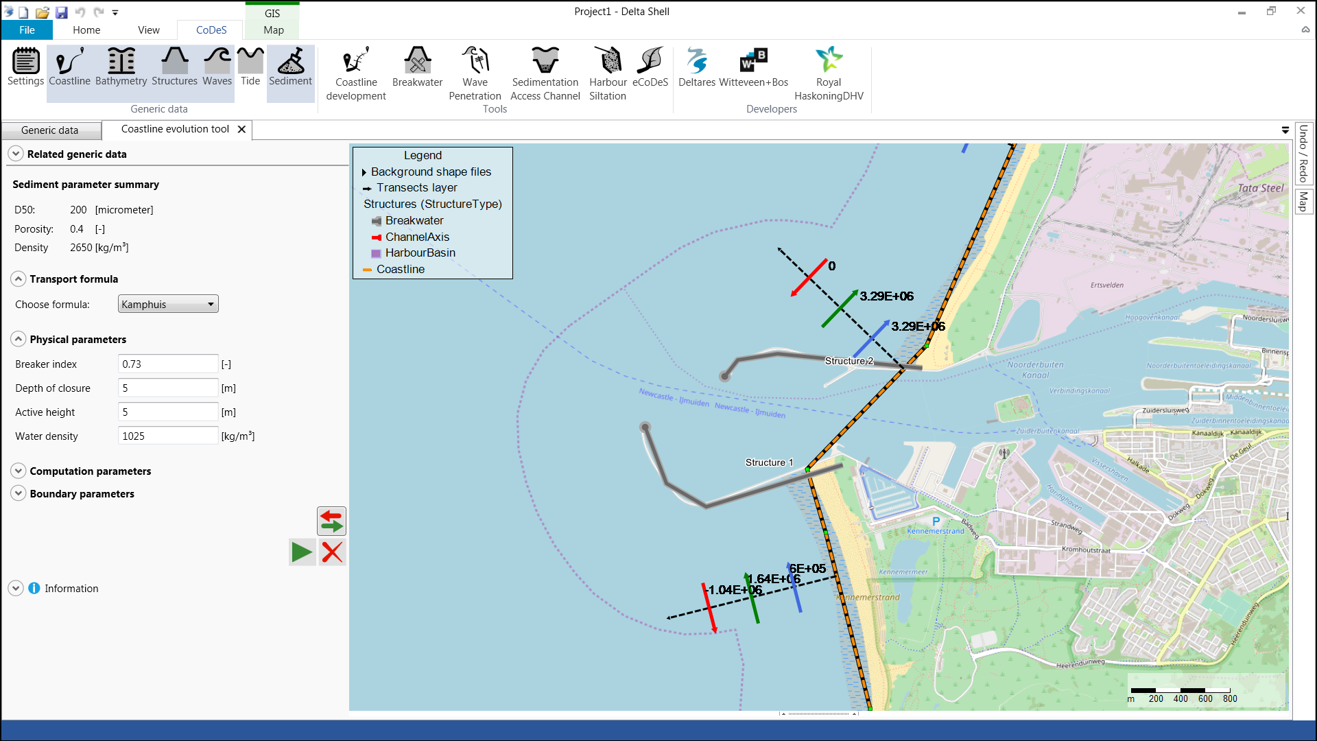
- Press the (
 ) button to obtain sediment transport magnitude information along a specified amount of shorenormal transects along the coastline.
- The Red arrow indicates the nett sediment transport magnitude in m3/year at the nett direction at that transect.
- The Green arrow indicates the gross sediment transport from left to right in m3/year at that transect.
- The Blue arrow indicates the gross sediment transport in m3/year from right to left at that transect.
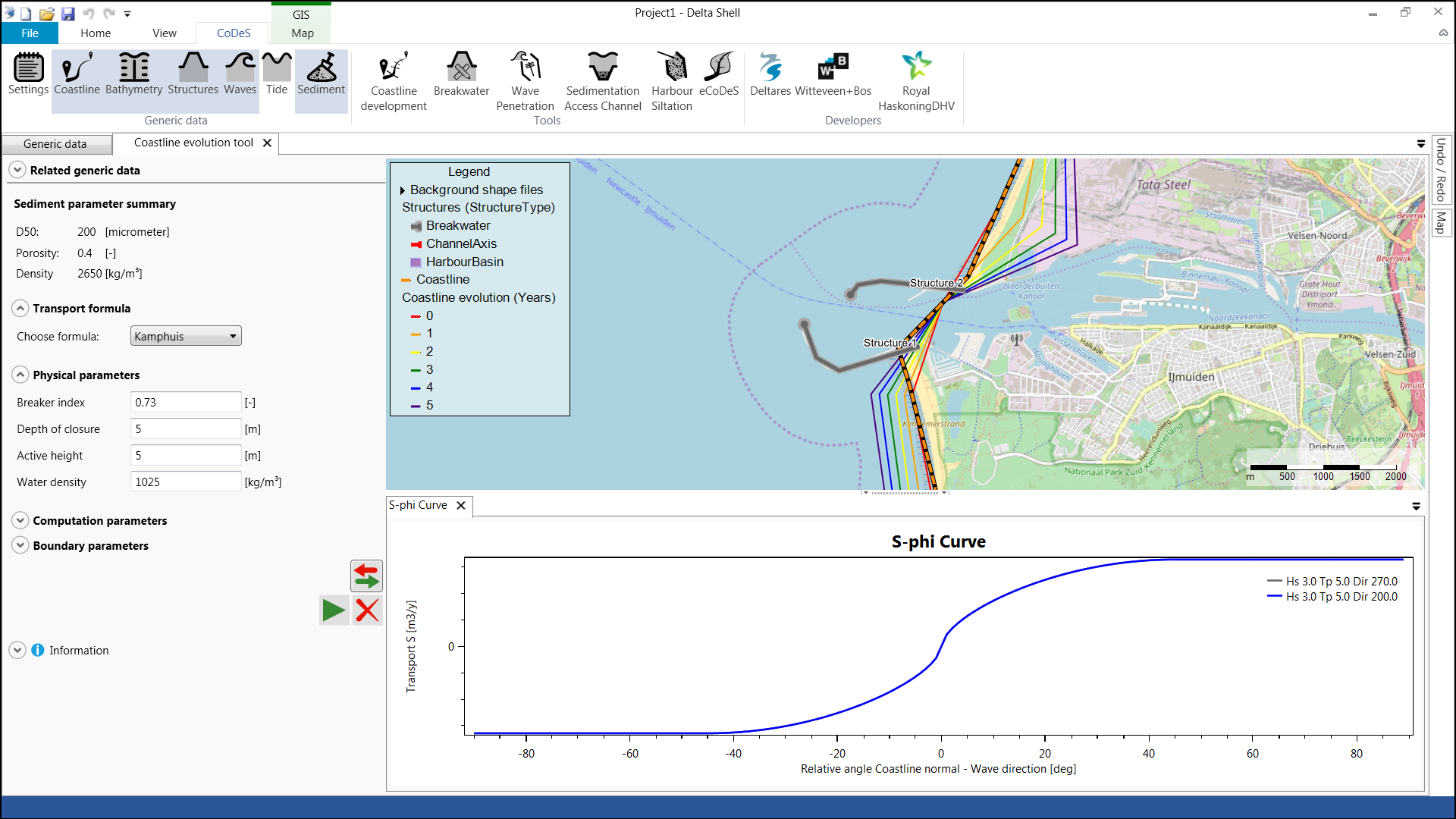
- Press the play button to start the coastline evolution calculation. A shoreline will be plotted on the map for each speficied time interval. An S-phi curve is plotted per wave condition.
- Press the delete button to delete the coastlines from the map.
Please be aware that the speed of this tool scales:
- Kwadraticly (!) with dx (based on distance of coast and/or number of points N)
- Linearly with with the maximum sediment transport in the S-phi curves (non-linearly with Hs and Tp)
- Linearly with the number of wave conditions
- Linearly with the active height
- Linearly with the duration of the computation
E.g.: when increasing both the number of gridpoints and the run-period by a factor 2, the computation will take 8x longer (!)
User input fields
A number of user input fields are provided which can be used to adjust the calculation according to the local situation. Default values are provided for each input field. The following inputs are defined:
Sediment parameter summary
- This section provides an overview of the sediment characteristics (, Porosity and ) used for the sediment transport calculation. Their values can be changed in the Sediment input in Generic Data.
| Default Value | Unit | Min. | Max. | Brief Description | |
|---|---|---|---|---|---|
| D50 | 200 | μm | 1 | 2.000 | Median grain size |
| Porosity | 0.4 | - | 0 | 1 | Fraction of voids |
| Density | 2.650 | kg/m3 | 1.000 | 5.000 | Bulk sediment density |
Transport formula
- Select the transport formula that is used for the sediment transport calculation. You can choose between Kamphuis or CERC.
Physical parameters
- Breaker index - Defines the wave height at which waves start to break. The maximum wave height is defined by the breaker index times the local waterdepth. Value should be between 0.0001 and 1.
- Depth of closure - Maximum waterdepth at which waves still induce sediment transport. Beach volume changes are calculated up to this waterdepth. Value should be between 0.0001 and 30 m.
- Active height - Maximum height of the dry beach which can still be considered active by sediment transport gradients. Beach volume changes are calculated up to this active height. Value should be between 0.0001 and 40 m
- Water density - Value should be between 1000 kg/m3 (e.g. fresh water) and 1025 kg/m3 (e.g. salty water).
Computation parameters
- N points - The number of points on the staggered grid. A staggered grid with an equal grid spacing according to the number of points is defined along the coastline. Value should be between 1 and 999.
- Total time - The total number of years for the simulation. Value should be between 1 and 1000 years.
- Time interval - The number of years after which a calculated shoreline position will be plotted on the map. Value should be between 1 and 20 years.
Boundary parameters
- Left and right boundary - Define the boundary condition applied on the left (closest to the coastline origin/blue arrow) and right boundaries of the staggered grid. You can choose between:
dS = 0 - the sediment transport on the boundary cell equals the sediment transport on the left/right most grid cell.
S = 0 - no sediment transport on the boundary cell.
Tool limitations
The following processes are not included in the tool: wave shadow zoning, alongshore varying wave climates, by-passing of breakwaters, non-linear beach profiles etc.
Results in terms of alongshore transports and coastline dynamics should therefore be interpreted with a considerable range of uncertainty.
Example cases
The following files (.dsproject) can be downloaded and loaded into CoDeS to serve as examples. They are not based on actual projects, but are intended as illustration.
Unzip the files to an convient folder (but make sure the file structure does not change), and open the .dsproject file from within CoDeS.