Contents
The export option "Riemann boundary calculation constants" in the F12 menu is a configuration aid for the Riemann boundary transformation. Given a coarse and a fine grid (both already configured in Grids.xml), and a set of boundary locations (already configured in LocationSets.xml), FEWS will calculate the constants, such as weights and angles, necessary to perform the Riemann boundary transformation to interpolate a time series from the coarse grid to the given boundary locations. The calculated constants will be exported to several CSV files, which can then be used to configure the necessary location attributes for the transformation.
Running the Calculation
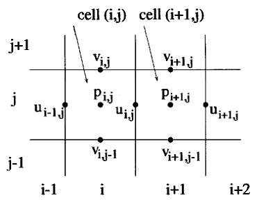
When the option is selected in the F12 menu, a menu in which the input grids and location set can be selected will appear. This menu will contain drop-down menus for the fine grid, coarse grid and boundary location set. Note that only regular, rectangular or quadrilateral grids which are not time-dependent will appear as an option for both the fine grid and the coarse grid. As indicated by their names, cells of the fine grid should be smaller then cells of the coarse grid. In the location set drop-down menu, only location sets which are not time-dependent will appear. Finally, a check-box can be selected if the coarse grid should be considered staggered. In this case the weights for u vectors, v vectors and time series located at the center point of the grid cell are calculated separately to reflect the different positions at which they are located:
After confirming the input options, a second menu will appear to select the output directory. Note that this directory should be empty.
Calculated Constants
The following constants are calculated (in the order they appear).
Border
For each boundary location, the fine grid cell containing this boundary location is found. This cell should be on the border of the fine grid. FEWS then checks whether an upper, lower, left and/or right cell are present, to determine the border the cell is on, which will be used in the Riemann boundary transformation. The outputted value will be UP, DOWN, LEFT or RIGHT. Note that the orientation of the grid is interpreted as depicted in the image above, i.e., the cell at row 0 and column 0 is viewed as the bottom left corner of the grid.
Note that for the remaining calculation to be successful, each fine grid cell found should always have either an upper or a lower neighboring cell, and either a left or a right neighboring cell. If this is not the case, a warning is logged and the remaining calculation for the boundary location will be skipped.
Angle
For each boundary location, the fine grid cell containing this boundary location is found. Then, the coarse grid cell containing the center of the fine grid cell is found. The angle between these two cells is calculated by first attempting to calculate the staggered v-position, and if this fails the staggered u-position for both cells. The calculation for the staggered v-position will fail if the coarse grid cell has neither an upper, nor a lower neighboring cell. The staggered u-position calculation will fail if the coarse grid cell has neither a left nor a right neighboring cell. If both calculations fail, a warning will be logged and the remaining calculation for the boundary location will be skipped.
To calculate the angle, the orientation of the grid cells is interpreted as a vector (arrow) from the centers of the grid cell to the staggered points. The angle between these two vectors is then calculated. The result can be interpreted as the angle with which the fine grid cell should be rotated clockwise, to result in an orientation exactly equal to the orientation of the coarse grid cell, as depicted by the two examples below. The angle will always be between -180 and 180 degrees.


Weights
For each boundary location, the fine grid cell containing this boundary lcoation is found. Then the coarse grid cell containing the center of the fine grid cell is found. To calculate the weights for time series located at the center of the grid points, FEWS calculated the distance between the center of the fine grid cell and the center of coarse grid cell and its eight direct neighbors. If the coarse grid is marked as staggered by the user, FEWS will calculate the weights for time series located at the staggered u and v points seperately. In these cases, the distance between the fine grid cell center and the staggered u or v-points of the containing coarse grid cell and its 15 surrounding cells is calculated. For the closest, two closest or four closest coarse grid cells, the weight is calculated as the inverse distance (1 / distance).
To decide whether only the closest coarse grid cell, the two closest coarse grid cells of the four closest coarse grid cells should be outputted, FEWS first calculates the minimum of the distance between the closest coarse grid cell center and its staggered u and v points. A distance tolerance is then calculated as 10% of this minimum. If the distance between the fine grid cell center and the closest coarse grid point is smaller than this distance tolerance, only the closest coarse grid cell is used. If the distance between the fine grid cell center and the line between the two closest coarse grid points is smaller than this distance tolerance, only the two closest coarse grid cells are used. If neither is the case, the four closest coarse grid cells are used.
Exported Files
Depending on whether the input coarse grid is staggered (and if any of the calculations were successfull) up to five csv files can be produced. Note that the in the file names "locset_id" will be replaced with the id of the boundary location set, and "coarse_grid_id" will be replaced with the id of the coarse grid.
locset_id_LocationSet.csv
This csv-file will contain six columns:
- BOUNDARY_LOCATION_ID
- BORDER
- ANGLE
- FINE_GRID_CELL: the cell index of the fine grid cell associated with this boundary location. Note that <cellIndex> = <rowIndex> * <totalColumns> + <columnIndex>.
- CELL_CENTER_X: the x-coordinate of the fine grid cell center, given in the geodatum of the fine grid.
- CELL_CENTER_Y: the y-coordinate of the fine grid cell center, given in the geodatum of the fine grid.
Note that since FEWS uses the fine grid cell centers to calculate the distances and therefore to calculate the weights, if the coordinates of the boundary locations were not equal to these cell centers, the boundary location coordinates should be replaced with the coordinates given in this csv file. This file can be used as the new csv-file from which to define the boundary location set in LocationSets.xml.
coarse_grid_id_LocationSet.csv
This csv-file will contain three columns:
- COARSE_GRID_LOCATION_ID: constructed using <coarse_grid_id>_<cellIndex>, for example: "my_grid_12". These will correspond exactly to the COARSE_GRID_LOCATION_ID columns in the attribute files containing the weights.
- CELL_CENTER_X: the x-coordinate of the coarse grid cell, given in the geodatum of the coarse grid.
- CELL_CENTER_Y: the y-coordinate of the coarse grid cell, given in the geodatum of the coarse grid.
It will contain a single entry for exactly those coarse grid cells for which a weight was calculated at least once. This file can be used to configure a new location set containing exactly those coarse grid locations for which a time series is needed to run the Riemann boundary transformation.
locset_id_AttributeFile_Center.csv & locset_id_AttributeFile_U.csv & locset_id_AttributeFile_V.csv
Note that locset_id_AttributeFile_U.csv and locset_id_AttributeFile_V.csv are only produced when the coarse grid was marked staggered. Each of these files will contain three columns:
- BOUNDARY_LOCATION_ID
- COARSE_GRID_LOCATION_ID: constructed using <coarse_grid_id>_<cellIndex>, for example: "my_grid_12". These will correspond exactly to the COARSE_GRID_LOCATION_ID column in the coarse grid location set file.
- WEIGHT
The files will contain one row for each calculated weight. Each boundary location (for which the calculation was run succesfully) can appear once, twice or four times, depending on the number of closest coarse grid cells found in the weight calculation. These files can be used to define two multi-value attributes for the boundary location set, containing the coarse grid locations needed to perform the Riemann boundary transformation for a boundary location and their weights respectively.
Riemann Boundary Transformation Configuration Example
Given the files outputted by the Riemann boundary constants export, the following could be added to LocationSets.xml to configure the coarse grid location set and boundary locations set with the attributes needed for the Riemann boundary transformation:
	<locationSet id="coarse_grid_locations">
		<description>Locations in the coarse grid needed for the Riemann boundary transformation</description>
		<csvFile>
			<file>coarse_grid_id_LocationSet.csv</file>
			<id>%COARSE_GRID_LOCATION_ID%</id>
			<x>%CELL_CENTER_X%</x>
			<y>%CELL_CENTER_Y%</y>
		</csvFile>
	</locationSet>
	<locationSet id="boundary_locations">
		<description>Boundary locations for the Riemann boundary transformation</description>
		<csvFile>
			<file>locset_id_LocationSet.csv</file>
			<id>%BOUNDARY_LOCATION_ID%</id>
			<x>%CELL_CENTER_X%</x>
			<y>%CELL_CENTER_Y%</y>
			<attribute id="angle">
				<number>%ANGLE%</number>
			</attribute>
			<attribute id="border">
				<text>%BORDER%</text>
			</attribute>
			<attributeFile>
				<csvFile>locset_id_AttributeFile_Center.csv</csvFile>
				<id>%BOUNDARY_LOCATION_ID%</id>
				<attribute id="center_coarse_grid_id">
					<text>%COARSE_GRID_LOCATION_ID%</text>
				</attribute>
				<attribute id="center_weight">
					<number>%WEIGHT%</number>
				</attribute>
			</attributeFile>
			<attributeFile>
				<csvFile>locset_id_AttributeFile_U.csv</csvFile>
				<id>%BOUNDARY_LOCATION_ID%</id>
				<attribute id="u_coarse_grid_id">
					<text>%COARSE_GRID_LOCATION_ID%</text>
				</attribute>
				<attribute id="u_weight">
					<number>%WEIGHT%</number>
				</attribute>
			</attributeFile>
			<attributeFile>
				<csvFile>locset_id_AttributeFile_V.csv</csvFile>
				<id>%BOUNDARY_LOCATION_ID%</id>
				<attribute id="v_coarse_grid_id">
					<text>%COARSE_GRID_LOCATION_ID%</text>
				</attribute>
				<attribute id="v_weight">
					<number>%WEIGHT%</number>
				</attribute>
			</attributeFile>
		</csvFile>
	</locationSet>