Measuring structures
Summary of structures
hymosincludes the following measuring structures:
Broad-crested weirs:
- Rectangular profile weir
- Roundnose horizontal crest weir
- Romijn movable measuring/regulating weir
- Triangular broad-crested weir
- Faiyum weir
Sharp-crested weirs: - Rectangular thin plate weir
- Triangular thin plate weir
- Cipoletti weir
Short-crested weirs: - Triangular profile or Crump weir
- Triangular profile Plat-V weir
- WES-spillway
- Cylindrical crested weir
- General weir (tidal/non-tidal sluice)
Flumes: - Rectangular throated flume
- Trapezoidal throated flume
- Rectangular/triangular/trapezoidal flume
- Truncated triangular flume
- Parabolic flume
- Circular flume
- U-throated flume
- Parshal flumes (22 types: 1" - 50')
- H-flumes (14 types: HS: 0.41 - 1.01 , H: 0.51 - 4.51 and HL: 3.51 - 4.01 )
In the following sections the structure discharge equation and the parameters are described.
In case your structure does not fit in the structures listed on the previous page reference is made to the hymosoption mentioned in section user defined structures which covers a more general type of structure equation.
Each structure has an equation which is applicable as long as the downstream water level is below a certain limiting water level know as the modular limit. The flows are therefore independent of the downstream water level, his is called free flow. The downstream water level is required in the calculations to determine if there is free flow. If the downstream water level do affect the flow, then the flow is known as drowned or submerged flow. Discharges under drowned conditions are obtained by applying a reduction factor to the free flow discharges. It is possible to disable the check on submerged flow, in this case the downstream water level is not required and the calculations are always under free flow conditions.
For most of the measurement structures the energy levels are used in the discharge calculations. These levels are not equal to the measured water levels. HYMOS can calculate the energy levels from the measured water levels by enabling the 'Include Velocity Head Correction' checkbox. When doing so a cross-section for the Upstream and Downstream water levels is required for calculating the energy level.

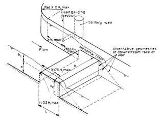
Figure Structure dimension and shape parameter descriptions
The entries can be stored in the database if so required.
Broad crested weirs
A broad-crested weir is an overflow structure with a horizontal crest above which the deviation from a hydrostatic pressure distribution because of centripetal acceleration may be neglected. In other words, the streamlines are practically straight and parallel. To obtain this situation the length of the weir crest in the direction of flow (L) should be related to the total energy head over the weir crest as 0.08 <= H1/L <= 0.50. H1/L >= 0.08 because otherwise the energy losses above the weir crest cannot be neglected, and undulations may occur on the crest. H1/L <= 0.50, so that only slight curvature of streamlines occurs above the crest and a hydrostatic pressure distribution may be assumed. The general equation for calculating discharges over a broad crested weir is:
Q = Ac { 2g (H1 - yc )}0.5

Rectangular profile weir (Herschy 1985, Bos 1978)

Parameters:
- hr = reference level
- P = height of weir
- L = length of weir
- b = width of weir
- h1 = upstream water level
- H1 = upstream energy level
- H2 = downstream energy level
Q = Cg . Cd . b .

Cd = 0.86 for h1 /P £0.5 and h1 /L £0.3
Cd = 0.888 - 0.093  + 0.133
  - 0.021 !03 - Stage
discharge^image058.gif! - 0.151 
+ 0.102  - 0.065
  + 0.310
+ 0.028!03 - Stage discharge^image068.gif! - 0.102!03 - Stage discharge^image070.gif!
The modular limit is obtained from:
H2 /H1 = 0.66 for H1 /L £0.33
H2 /H1 = 0.66 - 0.24 (H1 /L - 0.33) for 0.33 < H1 /L £1.5
H2 /H1 = 0.38 for H1 /L ³1.5
In case the modular limit is exceeded a missing value is entered for the discharge.
Round nose horizontal crest weir (Herschy 1985, Bos 1978)
Parameters:
- hr = reference level
- P = height of weir
- L = length of weir
- b = width of weir
- h1 = upstream water level
- H1 = upstream energy level
- H2 = downstream energy level
Q = Cg . Cd . b .
03 - Stage discharge^image052.gif!
03 - Stage discharge^image073.gif!
The modular limit is obtained from:
H2 /H1 = 0.855 + 0.070 ln (H1 /P) for H1 /P < 2
H2 /H1 = 0.869 + 0.049 ln (H1 /P) for H1 /P ³2
In case the modular limit is exceeded a missing value is entered for the discharge.
Romijn movable measuring/regulating weir

Parameters:
- hr = reference level
- L = length of weir
- b = width of weir
- h1 = upstream water level
- H1 = upstream energy level
- H2 = downstream energy level
Q = Cg . Cd . b .
Cd = 0.9564 + 1.018!03 - Stage discharge^image077.gif! - 3.530!03 - Stage discharge^image079.gif!
+ 4.936!03 - Stage discharge^image081.gif! - 2.302!03 - Stage discharge^image083.gif!
The validity range for calculating the Cd values is : 0.08 < < 0.78
The modular limit is obtained from:
H2 /H1 = 0.30
In case the modular limit is exceeded a missing value is entered for the discharge.
Triangular broad-crested weir

Parameters: - hr = reference level
- P = height of vertex above the bottom
- L = length of weir
- b = width of weir
- htr = height of triangle
- H1 = upstream energy level
- H2 = downstream energy level
Two cases are distinguished:
a. H1 £1.25 htr , then:
Q = Cg Cd

b. H1 > 1.25 htr , then:


Cd = 0.764 + 1.895  - 6.204 {~}
 + 6.944
  for!03 - Stage discharge^image097.gif! £0.25
Cd = 0.937 + 0.089 for  > 0.25
The modular limit is obtained from:
for H1 £1.25 htr : H2 /H1 = 0.80
for H1 > 1.25 htr : equations for the round nose horizontal crest weir with
P replaced by P + 1/2 htr
In case the modular limit is exceeded a missing value is entered for the discharge.
Faiyum weir

Parameters:
- hr = reference level
- L = length of weir
- b = width of weir
- h1 = upstream water level
- H1 = upstream energy level
- H2 = downstream energy level
Q = Cg . Cd . b .
03 - Stage discharge^image052.gif!
Cd = 0.848 for h1 /L < 0.43
Cd = 0.765 + 0.194 - 0.0003 for h1 /L ³0.43
The modular limit is given by equations of the rectangular profile weir. In case the modular limit is exceeded a missing value is entered for the discharge.
Sharp crested weirs
If the crest length in the direction of flow of a weir is short enough not to influence the head-discharge relationship of this weir (H1 /L greater than about 13) the weir is called sharp-crested or thin-plated. In practice, the crest in the direction of flow is generally equal to or less than 0.002 meter so that even at a minimum head of 0.03 meter the nappe can occur.

For the derivation of the head-discharge equations it is assumed that sharp-crested weirs behave like orifices with a free water surface, and the following assumptions are made: - The height of the water level above the weir crest is h=h1 and there is no contraction.
- Velocities over the weir crest are almost horizontal.
- The approach velocity head v1 2 /2g is neglected.
The general head-discharge equation of a sharp-crested weir reads:
03 - Stage discharge^image103.gif!
Rectangular thin plate weir (Herschy 1985)

Parameters:
- hr = reference level
- P = height structure
- b = width of weir
- B = width of channel
- ha = height of opening
- h1 = upstream water level
Q = Cg . Cd . be .

Cd = a+ b
where:
a = 0.587 + 0.01 b/B for b/B £0.7
a = 0.610 - 0.056 + 0.048
  for b/B > 0.7
b = -0.002 for b/B £0.2
b = 0.0016 - 0.0367 + 0.1127 for b/B > 0.2
he = h1 + 0.001
be = b + 0.003
The following limitations apply on the use of the above formulae:
b ³0.15 m
P ³0.10 m
he ³0.03 m
h1 /P £2.0
h1 £ha and h2 £-0.05 m
Triangular thin plate weir
03 - Stage discharge^image118.jpg!
Parameters: - hr = reference level
- b = width of triangle
- htr = height of triangle
- h1 = upstream water level
- h2 = downstream water level
Q = Cg . Cd .

Cd = 0.640 - 0.873 h1 + 5.101  - 13.040
  + 12.311
  for q= 900
Cd = 0.637 - 0.566 h1 + 2.758 - 6.425!03 - Stage discharge^image126.gif! + 5.753 for q= ½ 900
Cd = 0.612 - 1.288 h1 + 6.804 - 16.686!03 - Stage discharge^image126.gif! + 15.345 for q= ¼ 900
Cd = 0.614 - 0.074 q+ 0.046 q2 - 0.009 q3 for 200 £ q £1000
(qin radians)
The following limitations apply on the use of the above formulae:
h1 £htr
h1 £0.60 m and h2 £-0.05 m
Cipoletti weir

Parameters:
- hr = reference level
- b = width of sill of aperture
- h1 = upstream water level
- H1 = upstream energy level
- h2 = downstream water level
Q = Cg . Cd . b .

Cd = 0.63
The following limitations apply on the use of the above formulae:
h1 /b £0.5
h1 £0.60 m and h2 £-0.05 m
Short crested weirs
The basic difference between a broad-crested weir and a short-crested weir is that nowhere above the short crest can the curvature of the streamlines be neglected; there is thus no hydrostatic pressure distribution
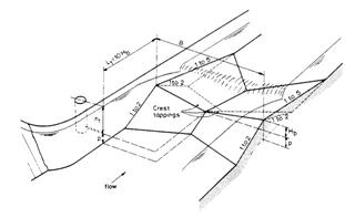
Triangular profile or Crump weir (Herschy, 1985)

Parameters: - hr = reference level
- P = height of weir
- b = width of weir
- h1 = upstream water level
- H1 = upstream energy level
- h2 = downstream water level
Q = Cg . Cd . b .

Cd = 0.633
The modular limit h2 /h1 = 0.75. If this value is exceeded a missing value will be entered for the discharge. Further limiting conditions are:
P ³0.06 m
b ³0.30 m
h1 /P £3
b/h1 ³2
Triangular profile flat-V weir (Herschy, 1985)
Parameters: - hr = reference level
- b = width of structure
- htr = height of triangle
- h1 = upstream water level
- H1 = upstream energy head
- h2 = downstream water level
For h1 £htr :
Q = Cg . Cd . m .
03 - Stage discharge^image142.gif!
Cd = 0.615 for m £15
Cd = 0.620 for 15 < m < 30
Cd = 0.625 for m ³30
m = b/2htr
For h1 > htr :

Cd = 0.620 for m £15
Cd = 0.625 for 15 < m < 30
Cd = 0.630 for m ³30
The modular limit is:
for h1 £htr h2 /h1 = 0.70
for h1 > htr h2 /h1 = 0.75
If the modular limit is exceeded a missing value will be entered for the discharge.
wes*-spillway (Bos, 1978)*

Parameters: - hr = reference level
- P = height of spillway
- b = width of spillway
- x = slope parameter (x = 0: vertical)
- h1 = upstream water level
- H1 = upstream energy head
- H2 = downstream energy level
Q = Cg . Ce . b .

Ce = C0 . C1 . C2
C0 = 1.3
C1 = 0.693 + 0.516!03 - Stage discharge^image150.gif! - 0.438!03 - Stage discharge^image152.gif! + 0.089!03 - Stage discharge^image154.gif! ,P/h1 £0.2
C1 = 0.692 + 0.521!03 - Stage discharge^image150.gif! - 0.311!03 - Stage discharge^image152.gif! + 0.063!03 - Stage discharge^image154.gif! ,P/h1 = 0.33
C1 = 0.6907 + 0.544!03 - Stage discharge^image150.gif! - 0.313!03 - Stage discharge^image152.gif! + 0.056!03 - Stage discharge^image154.gif! ,P/h1 = 0.67
C1 = 0.6906 + 0.544!03 - Stage discharge^image150.gif! - 0.309!03 - Stage discharge^image152.gif! + 0.063!03 - Stage discharge^image154.gif! ,P/h1 = 1.00
C1 = 0.6896 + 0.553!03 - Stage discharge^image150.gif! - 0.307!03 - Stage discharge^image152.gif! + 0.061!03 - Stage discharge^image154.gif! ,P/h1 ³1.33
For values of P/h1 in between 0.2 and 1.33 linear interpolation between the above formulae is applied.
C2 = 1.00 for x = 0
C2 = 1.012 - 0.0136!03 - Stage discharge^image157.gif! + 0.0038!03 - Stage discharge^image159.gif! for x = 1
C2 = 1.033 - 0.0379!03 - Stage discharge^image157.gif! + 0.0139!03 - Stage discharge^image159.gif! for x = 2
C2 = 1.050 - 0.0861!03 - Stage discharge^image157.gif! + 0.0333!03 - Stage discharge^image159.gif! for x = 3
The modular limit H2 /H1 = 0.3. If this value is exceeded, the discharge is reduced by a factor f:
f = 1.097 - 0.6796!03 - Stage discharge^image161.gif! + 1.438!03 - Stage discharge^image163.gif! - 1.159!03 - Stage discharge^image165.gif! for 0.3 < £0.80
£0.80
f = 20.327 - 78.274 * + 105.57!03 - Stage discharge^image163.gif! - 47.630!03 - Stage discharge^image165.gif! for!03 - Stage discharge^image167.gif! > 0.8
Cylindrical crested weir (Bos, 1978)
03 - Stage discharge^image169.jpg!
Parameters: - hr = reference level
- P = height of weir
- b = width of weir
- x = slope parameter (x = 0: vertical)
- r = radius of weir sill
- H1 = upstream energy level
- H2 = downstream energy level
Q = Cg . Ce . b .
03 - Stage discharge^image148.gif!
Ce = C0 . C1 . C2
C0 = 1.1846 + 0.1318 ln (H1 /r) for!03 - Stage discharge^image171.gif! < 0.88
C0 = 1.1922 + 0.1915 ln (H1 /r) for 0.88 £ < 4.8
< 4.8
C0 = 1.49 for!03 - Stage discharge^image171.gif! ³4.8
C1 = 0.9764 + 0.0914 ln (P/H1 ) for!03 - Stage discharge^image173.gif! < 1.0
C1 = 0.9352 + 0.0494!03 - Stage discharge^image157.gif! + 0.00927!03 - Stage discharge^image159.gif! for 1 £ £2.4
£2.4
C1 = 1.000 for!03 - Stage discharge^image173.gif! > 2.4
C2 is given by the equations for the Wess spillway.
The modular limit H2 /H1 = 0.33. For higher values of H2 /H1 the discharge according to the first equation is reduced by a factor f:
f = 1.224 - 1.671!03 - Stage discharge^image161.gif! + 3.605!03 - Stage discharge^image163.gif! - 2.829!03 - Stage discharge^image165.gif! for 0.33 < < 0.85
f = 5.361 - 20.649!03 - Stage discharge^image161.gif! + 32.105!03 - Stage discharge^image163.gif! - 16.789!03 - Stage discharge^image165.gif! for!03 - Stage discharge^image167.gif! ³0.85
General weir

Parameters: - hr = reference level
- h1 = upstream water level
- h2 = downstream water level
- hg = gate level or sill
- b = structure width
For sub-critical flow:
Q =
For critical flow:
Q =
with:
A1 = B(h2 - hg )
A2 =
Flumes
A critical depth-flume is essentially a geometrically specified constriction built in an open channel where sufficient fall is available for critical flow to occur in the throat of the flume. Flumes are 'in-line' structures, i.e. their centre line coincides with the centre line of the undivided channel in which the flow is to be measured.
Rectangular throated flume (Herschy, 1985)

Parameters:
- hr = reference level
- L = length of flume
- b = width of flume throat
- ml = modular limit
- h1 = upstream water level
- H1 = upstream energy level
Q = Cg . Cd . b .
03 - Stage discharge^image148.gif!
Cd =
The modular limit is input, (generally in the order of 0.85 - 0.95). If the modular limit is exceeded a missing value is entered for the discharge.
!h3. Trapezoidal throated flume (Herschy, 1985)
03 - Stage discharge^image187.jpg!
Parameters: - L = length of flume
- b = width of throat bottom
- m = side slope
- ml = modular limit
- h1 = upstream water level
- H1 = upstream energy level
Q = Cg . Cd . Cs . b .
Cd =
where:
x = 0.972 - 0.878 m + 0.366 m2 - 0.0543 m3 for m £2
x = 0.438 - 0.127 m + 0.015 m2 - 0.5976 m3 for m > 2
Cs = 1.002 + 0.678 y + 0.0327 y2 - 0.065 y3 for y £3
Cs = 0.088 + 1.144 y - 0.0488 y2 - 0.0016 y3 for y > 3
with:
y = m h1 /b
The modular limit is input, (generally in the order of 0.85 - 0.95). If the modular limit is exceeded a missing value is entered for the discharge.
Rectangular/triangular/trapezoidal flume (Bos, 1978)
03 - Stage discharge^image191.jpg!
Parameters: - hr = reference level
- L = length of flume
- b = width of throat bottom
- m = side slope
- ml = modular limit
- H1 = upstream energy level


Cd = 0.845 + 0.726!03 - Stage discharge^image077.gif! - 1.563!03 - Stage discharge^image079.gif! + 1.156!03 - Stage discharge^image081.gif! for!03 - Stage discharge^image097.gif! £0.5
Cd = 0.957 - 0.017!03 - Stage discharge^image077.gif! + 0.046!03 - Stage discharge^image079.gif! + 0.017!03 - Stage discharge^image081.gif! for!03 - Stage discharge^image097.gif! > 0.5
yc = for m = 0
yc = for m > 0
Following profiles can be covered:
b > 0 and m = 0 rectangular flume
b = 0 and m > 0 triangular flume
b > 0 and m > 0 trapezoidal flume
The modular limit is input, (generally in the order of 0.85 - 0.95). If the modular limit is exceeded a missing value is entered for the discharge.
Truncated triangular flume (Bos, 1978)

Parameters: - hr = reference level
- L = length of flume
- b = width of flume
- htr = height of triangle
- ml = modular limit
- H1 = upstream energy level
 for H1 £

Cd is given by the rectangular flume equations
m = b/2htr
 for H1 >
Cd is given by the rectangular flume equations
The modular limit is input. If the modular limit is exceeded a missing value is entered for the discharge.
Parabolic flume (Bos, 1978)
03 - Stage discharge^image215.jpg!
Parameters: - hr = reference level
- L = length of flume
- f = shape parameter
- ml = modular limit
- H1 = upstream energy level
Q = Cg Cd Öf!03 - Stage discharge^image217.gif!
03 - Stage discharge^image219.gif!
Cd is given by the rectangular flume equations
The modular limit is input. If the modular limit is exceeded a missing value is entered for the discharge.
Circular flume (Bos, 1978)
03 - Stage discharge^image221.jpg!
Parameters:
1. hr = reference level
2. L = length of flume
3. d = diameter of flume
4. ml = modular limit
5. H1 = upstream energy level
03 - Stage discharge^image223.gif!
03 - Stage discharge^image195.gif!
Cd is given by the rectangular flume equations
yc = H1 {0.75183 - 0.04410!03 - Stage discharge^image226.gif! + 0.02578!03 - Stage discharge^image228.gif! - 0.04568!03 - Stage discharge^image230.gif! } for!03 - Stage discharge^image232.gif! £1
yc = H1 {0.52496 + 0.53698!03 - Stage discharge^image226.gif! - 0.46709!03 - Stage discharge^image228.gif! - 0.09393!03 - Stage discharge^image230.gif! } for 1 < £1.8
£1.8
yc = H1 {1.0505 - 0.34016!03 - Stage discharge^image226.gif! + 0.01743!03 - Stage discharge^image228.gif! - 0.005307!03 - Stage discharge^image230.gif! } for!03 - Stage discharge^image232.gif! > 1.8

a= 2. arccos (1 - 2 yc /d)
The modular limit is input. If the modular limit is exceeded a missing value is entered for the discharge.
U-throated flume (Bos, 1978)

Parameters: - hr = reference level
- L = length of flume
- d=b = width of flume
- ml = modular limit
- H1 = upstream energy level
For H1 < 0.7 d the formulae of the circular flume apply.
For H1 ³0.7 d the discharge is computed by:
03 - Stage discharge^image246.gif!
03 - Stage discharge^image248.gif!
Cd is given by the rectangular flume equations
The modular limit is input. If the modular limit is exceeded a missing value is entered for the discharge.
Parshall flumes

Parameters: - hr = reference level
- npf = throat width number (see below)
- h1 = upstream water level
- h2 = downstream water level
The general discharge equation is of the form:

K and u follow from the underneath Table.
Table Parameters of the discharge equation of Parshall flumes
width npf K u ml p a b c mf
1" 1 0.0604 1.55 0.50 1.64 -4.5837 11.118 -4.8464 1.0*10-3
2" 2 0.1207 1.55 0.50 1.48 -5.2025 12.141 -5.1189 1.0*10-3
3" 3 0.1771 1.55 0.50 1.65 -5.3387 12.834 -5.3693 1.0*10-3
6" 4 0.3812 1.58 0.60 1.57 -1.6117 5.3856 -1.3952 1.0*10-3
9" 5 0.5354 1.53 0.60 1.50 -4.2328 10.747 -4.0566 1.0*10-3
1' 6 0.6909 1.522 0.70 1.54 -5.0446 5.5661 -0.80775 1.0*10-3
1'6" 7 1.506 1.538 0.70 1.54 -5.0446 5.5661 -0.80775 1.4*10-3
2' 8 1.428 1.550 0.70 1.54 -5.0446 5.5661 -0.80775 1.8*10-3
3' 9 2.184 1.566 0.70 1.54 -5.0446 5.5661 -0.80775 2.4*10-3
4' 10 2.953 1.578 0.70 1.54 -5.0446 5.5661 -0.80775 3.1*10-3
5' 11 3.732 1.587 0.70 1.54 -5.0446 5.5661 -0.80775 3.7*10-3
6' 12 4.519 1.595 0.70 1.54 -5.0446 5.5661 -0.80775 4.3*10-3
7' 13 5.312 1.601 0.70 1.54 -5.0446 5.5661 -0.80775 4.9*10-3
8' 14 6.112 1.607 0.70 1.54 -5.0446 5.5661 -0.80775 5.4*10-3
10 ' 15 7.463 1.60 0.80 2.00 -26.086 49.689 -23.103 1.0
12' 16 8.859 1.60 0.80 2.00 -26.086 49.689 -23.103 1.2
15' 17 10.96 1.60 0.80 2.00 -26.086 49.689 -23.103 1.5
20' 18 14.45 1.60 0.80 2.00 -26.086 49.689 -23.103 2.0
25' 19 17.94 1.60 0.80 2.00 -26.086 49.689 -23.103 2.5
30' 20 21.44 1.60 0.80 2.00 -26.086 49.689 -23.103 3.0
40' 21 28.43 1.60 0.80 2.00 -26.086 49.689 -23.103 4.0
50' 22 35.41 1.60 0.80 2.00 -26.086 49.689 -23.103 5.0
The modular limit ml varies from 0.5 to 0.8. In case this limit is exceeded the discharge is reduced with the quantity Qe , where:

q = with S = h2 /h1
The parameters ml , mf , a, b and c are presented in the Table. The corrected discharge then follows from:
Qc = Q - Qe
H-flumes

Parameters: - hr = reference level
- nH = flume depth number (see below)
- h1 = upstream water level
- h2 = downstream water level

The parameters a, b and c follow from the underneath table.
Table Parameters of the discharge equation of H-flumes
Type Depth nH a b c ml
HS 0.4' 1 -0.4361 2.5151 0.1379 0.25
HS 0.6' 2 -0.4430 2.4908 0.1657 0.25
HS 0.8' 3 -0.4410 2.4571 0.1762 0.25
HS 1.0' 4 -0.4382 2.4193 0.1790 0.25
H 0.5' 5 0.0372 2.6629 0.1954 0.25
H 0.75' 6 0.0351 2.6434 0.2243 0.25
H 1.0' 7 0.0206 2.5902 0.2281 0.25
H 1.5' 8 0.0238 2.5473 0.2540 0.25
H 2.0' 9 0.0237 2.4918 0.2605 0.25
H 2.5' 10 0.0268 2.4402 0.2600 0.25
H 3.0' 11 0.0329 2.3977 0.2588 0.25
H 4.5' 12 0.0588 2.3032 0.2547 0.25
HL 3.5' 13 0.3081 2.3935 0.2911 0.30
HL 4.0' 14 0.3160 2.3466 0.2794 0.30
The modular limit is presented in the last column of the table. If this limit is exceeded, a missing value is entered for the discharge.
Application
Select the function <Measurement-Structure> from the Flow Measurements functions map. The required entries to run this function comprise:
Series Codes
Select a Discharge series by highlighting the series in the series list and pressing <Select> next to the discharge series textbox. HYMOSwill extract all relations for this series from the database and place them in the relations list box on the form.
You can now add a new relation or use an existing relation. If you want to use an existing relation, choose the relation from the relation list box.
Structure equation
Select a structure equation by selecting the appropriate tab of the measurement structures spreadsheet and select the row with the type of structure. HYMOSwill now present all input fields for the selected equation type.
Transformation period
By double-clicking the date textboxes you can change the validity time period of the transformation equation.
Add Relation
If all coefficients of the relation is entered you can save the relation to the database by pressing the <Add Relation> button.
After you made your selections press <Execute> and analyse the results as a graph, table and report. To show the graph on screen select <Graph> from the functions tab. To analyse the report press <Report> from the functions tab.
You can also Save the generated series by pressing the <Save> button or exporting the series by selecting <Export>.
Calculation of Discharges
When the form is loaded a discharge series must be selected from the series list box. HYMOSwill look in the database if a relation for the selected discharge series exists. If so it will show all relations in the relations list box. Structures have relations which are valid for a defined period, for each period a relation can be made. A period is defined by a start and end date of a rating equation. When a discharge series is selected a new relation can be made for a structure or an existing relation can be selected from the relations list box. When a new relation is made the user must also select an upstream water level and a downstream water level. The downstream water level is necessary for checking if there is submerged flow or free flow. When the user does not want a check on submerged flow, a downstream water level in not required.
For correction of the velocity head, a water level series must contain a cross-sectional profile. This profile is necessary to calculate energy levels from the measured water levels. Most measurement structure equations make discharge calculations based on energy levels. The cross-sectional profiles are measured profiles which can be entered in the Entry and Edit functions. These profiles are saved in the HYMOSdatabase with a link to the water level series.
For calculating discharges over a structure, including check on submergence and velocity head correction, HYMOSthus requires two water level series with for each water level series a cross-sectional profile. If cross-sectional profiles are not available in the database, HYMOSwill give a warning when pressing EXECUTE and stop the discharge calculation.
There is one structure, the 'General Weir' which requires also a gate level series for the calculation. This gate level series must be selected from the series list box.
While calculating the discharges it is possible that HYMOSwill return missing values. Missing values are returned in the following situations: - The upstream or downstream water levels are missing.
- If the date of the calculated discharge is outside the validity period of the relation.
- The upstream water level is above the structure height.
- The upstream water level is above the highest point of the upstream cross sectional profile.
- If the modular limit is exceeded.
- The downstream water level is above the highest point of the downstream cross sectional profile.
A zero discharge is returned when: - The upstream water level is below the Sill height of the structure.
- The upstream water level is below the lowest point of the upstream cross sectional profile.
- The downstream water level is below the lowest point of the downstream cross sectional profile.
General computation procedure
The general equation used for measurement structures is:

where:
H = total head
g = acceleration due to gravity
b = width
Cd = coefficient of discharge
As mentioned earlier the total head H cannot be measured in practice. Therefore an iterative procedure is included to compute the discharge from the measured head h . This iterative procedure is as follows:
1. The area of cross section flow A is computed from the cross-section profile data for the measured head h .
2. The discharge is computed with the discharge equation, using the measured head h instead of the total head H .
3. The total head H is computed from equations:

4. If the difference between the total head H and the measured head h is larger than 0.001 then the computed total head H is used and the computation is restarted in 1.
Sometimes this iterative procedure is not used to compute the discharge. Instead a dimensionless velocity coefficient Cv is used in the equation to correct for the velocity of approach. This coefficient Cv can be obtained from a table from the cross-sectional area and Cd bh.