A universal quantitative damage description for 3D rubble mound structures
1. Problem description
1.1. Problem analysis
The level of damage that may occur at RMS is difficult to determine. There is no single definition for a particular damage level and several damage parameters are developed. For each of these damage parameters the values are often determined for three levels of damage: initial damage, intermediate damage and failure.
Designers use these values to come to design example breakwaters. The values however are based on standard straight forward cases. Does the design become a bit more complex then the applicability of these values becomes uncertain. Partly for this reason, before breakwaters are executed in reality the design is tested on small scale in a research facility. This verification of the design makes sure that unforeseen processes doesn’t play a role.
1.1.1. Damage parameters
Damage to rubble mound structures (RMS) can be expressed by some (dimensionless) parameters. The most widely used parameters are Nd, Nod and S value . The Nd value is the amount of damage as a percentage of all armour rock; Nod is the number of stones eroded per Dn50 wide strip of breakwater and the S value is the relation between the eroded 2D vertical area divided by the Dn50 squared [CIRA et al., 2007].
Beside those parameters several other parameters are developed . One parameter regards the eroded depth (E), another to the thickness of the amour layer left over (C) and the last one depends on the length of the erosion area (L). These parameters are all made dimensionless by dividing by Dn50, which is the mean nominal rock diameter of the armour layer. Figure 1‑1 explains the other factors.
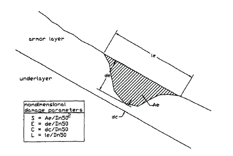
Figure 1‑1: Graphical overview of different damage parameters [Melby and Kobayashi, 1998]
For assessing the damage in flume experiments the average measured profile is taken into account. In this way, the average value for the damage parameter can be determined. To examine the variability of this mean value, which is caused mainly by the irregularity placement of the stones, each measured profile is compared with the mean profile. In the experiments and damage analysis done by Melby and Kobayashi, 1998 it shows that the value of each damage parameter is between the mean value plus three times the standard deviation and the mean minus three times the standard deviation of the particular parameter.
The most widely used and accepted damage parameter is the S value introduced by Broderick, 1983 and popularized by Van der Meer, 1988. However, this parameter (and many more) is based on cross-sectional profiles. Looking to tests all over the world, which had the purpose to determine damage parameters, the tested structure had a constant cross section. How this parameter and the other parameters will withstand in a 3D structure is still part of research.
1.1.2. Damage measurement techniques
To determine these damage parameters a survey of the slope profile is required. The so-called in-survey before a test and an out-survey after the test. When comparing these surveys with each other the damage parameters can be examined and determined.
Classically mechanical surface profilers are used to obtain these profiles for the surveys. These surface profilers have rods on a fixed distance. The rods give for a test section a limited number of profiles. In case of little damage, this method can be very inaccurate when single stones erode between the rods. To increase the accuracy, a profiler with smaller distances between the rods can be used.
Nowadays more accurate measurement techniques are available. A 3D high-resolution survey can be obtained by using a laser scanner or stereo photography. Until now, the biggest disadvantage of these techniques was that the whole basin needed to be flooded or emptied. This was necessary to compensate for the refraction at the water air transition. Latest development has eliminated this disadvantage. Therefore, these high-resolution techniques can give quick detailed information about the shape of the physical model. How to use and link this high-resolution survey data to the damage parameter is still part of research.
1.1.3. Damage to rubble mound breakwater roundheads
For testing new designs of breakwaters and especially breakwaters heads, physical testing is necessary due to the complex 3D shape of such a head. Some basic guidelines are applied to come to a preliminary design of a roundhead. As a first guideline the diameter of the roundhead should be at least twice the design wave height and secondly the stone diameter must be at least 25% larger compared with the trunk [CIRIA et al., 2007].

Figure 1‑2: Overview of the damage zone on breakwater roundheads
To test the preliminary design of breakwaters and especially roundheads, physical models are used. While testing the breakwater during design conditions, the trunk is tested for multiple sections, each section has the size of the damage gap. Each section can be seen as one realisation of a trunk test. In that way the trunk is artificially tested multiple times during the same wave conditions. While at the head, most likely, only one damage gap will occur and therefore only one test is realized for the roundhead. In addition, a physical test is only executed once due the high expenses for multiple tests. Therefore, the reliability of the outcome of a single test can be questionable.
1.2. Problem definition
Most of the damage parameters have different design values for different kind of structures, partly because these values depend on the slope or other parameters. Therefore, the ultimate goal is to determine for every RMS a damage parameter with universal design values.
1.3. MSc-thesis objective and approach
Due to the limited time, the focus of this thesis will be on the determination of a damage parameter with a universal design value for roundheads.
To come to the objective, a roundhead model test will be set up at the Deltares laboratory. To obtain a 3D high-resolution survey of the model, digital stereo photography (DSP) is used. Because DSP is a quite new technique, the interpretation of the survey results will be a goal. In addition, it is even more important to found out how to connect the high-resolution survey data to the damage parameter. Therefore, the damage will be assessed by existing parameters and a possible new (3D) damage parameter.
In order to check whether the damage to the heads is consistent, multiple identical roundheads are tested. Furthermore, the deviation of the damage parameter can be evaluated to assess the reliability of single testing to roundheads.
Info:
