Edit flow measurements
Flow Measurement Data
Flow measurements can be added with 'flow measurement data' function from the 'Edit and Entry' function map. The data entered or edited will not be stored in the HYMOS database but in separate files (extension *.flw).

The entered data includes:
- Measurement date and time
- Duration of measurement in minutes
- Observation Number
- Unit: metric or imperial
- Computation of total flow: mean section method, or mid-section method
- distance from reference point
- width of river
- level of gauge zero
- water level (rel. to gauge zero) at start of measurement
- water level at end of measurement
- water level difference with downstream station, only required if backwater correction is required, else 0.
- vertical number, distance from reference point and water depth
- measuring depth, number of rotations duration of single point measurement
- airline length, vertical angle, horizontal angle
To edit an existing flow measurement file, double-click on the filename text box and select a file with the windows file open dialogue.
Add a flow measurement by filling in the text boxes and making your selection concerning the discharge computation method and units. Enter the number of verticals and per vertical the number of measuring points. After entering all values give a filename and press <Save> to save your data.
Types of measurements
HYMOS can treat two types of flow measuring methods:
- point velocity method
- moving boat method.
In both cases average velocities in a number of verticals in the cross-section are computed. From these velocities the discharge is computed by:
- mean-section method
- mid-section method.
The computational results are presented in tables and graphs. The condensed results can be stored in the database.
Mean and mid-section methods
The flow velocity is measured in verticals at distances wi , i=1,m from a reference point on the river bank. The water depth at vertical i is denoted by di and the average flow velocity in that vertical by  , see the underneath figure.
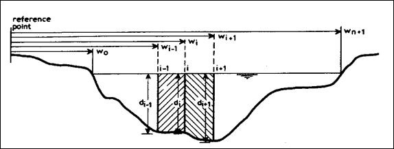
Figure 8.1: Definition sketch
Discharge computation
The discharge qi in section i-1 to i is computed from:
- Mean-section method:

- Mid-section method:

for i= 1,n+1, with:
do = dn+1 = 0
The total discharge then follows from:

If the water levels at the beginning and at the end of the measurements are denoted by h1 and h2 respectively, then the representative water level hQ is computed from:
- if |h1 - h2 | < 0.05 by: hQ = ½ (h1 + h2 )
- if |h1 - h2 | ³0.05 by:

To estimate the average velocity  in a vertical in the cross-section from point measurements vp at p * flow depth, following methods are available in hymos: (iso748 and iso/tr7178):
- one-point method:

- two-point method:

- three-point method:

- four-point method:

- five-point method:

- six-point method:

- profile method, see Figure


Figure 8.2: profile
The last term in the equation assumes an extrapolation of the velocity profile to the bottom according to the power profile
Air- and wet-line correction
hymosallows you to include air- and wet-line corrections in case the depths are measured with a wire, see figure.
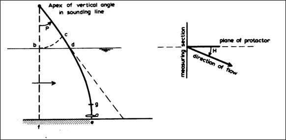
Figure 8.3: Air- and wet-line correction
The air-line correction cd is computed from:
cd = ab (sec (P) - 1)
where:
ab = air-line length
P = vertical angle in the sounding line
The vertical angle P is adjusted to the true vertical angle X in case the plane of the protactor makes a horizontal angle H with the direction of the flow according to:
X = arctan (tan(P)/cos(H))
The wet-line correction ge is expressed as a percentage aof the wet-line length de according to iso748-1979 (E) Annex C Table 2. So the true depth bf follows from:
bf = (ce - cd) (1 - a /100)
Moving boat method
In the moving boat method the combined boat- and river velocity is measured. To compute from this the actual river velocity either the angle between the current meter and the section line or the boat velocity is measured additionally.
Following methods are distinguished to compute the stream velocity in vertical i :
- vi = vv,i . sin ai
- vi =

where:
vi = point velocity in vertical i
vv,i = combined boat and stream velocity
ai = angle between current meter and section line
vb,i = boat velocity at vertical i
The stream velocity is measured at a constant depth wd below the water surface. This velocity is transformed into the average velocity in the vertical by assuming a power law velocity profile:

with:
= average stream velocity in vertical i
c = power of power law velocity profile (5 £c £7)
di = flow depth at vertical i
wd = current meter depth
Width adjustment
Since the sum of the segment widths B c may deviate from the actual river width B m the computed segment widths are adjusted by the ratio B m /B c in the calculations.
Layout of files
The Layout of the flow measurements file (.flw) is as follows
Line 1
Position
01 - 03 number of the measurement
04 - 07 year (yyyy) +
09 - 10 month (mm) +date of measurement
12 - 13 day (dd) +
15 - 16 hour (hh) +time of measurement at start
18 - 19 minute (mi) +
20 - 22 duration of measurement in minutes
25 unit: metric(0) or imperial(1)
28 type of measurement:
1-6 = point measurements according to ISO standard, where the type number corresponds with the number of points in the vertical
7 = point measurements with free distance between points in the vertical (number of points £10)
8 = moving boat: method vv-a
9 = moving boat: method vb-vv
31 comp. of total flow: 1= mean section method, or
2= mid-section method
Line 2 - Point velocity measurements (type £ 7).
Position:
01 -08 distance from reference point
09 -16 width of river
17 -24 level of gauge zero
25 -32 water level (rel. to gauge zero) at start of measurement
33 -40 water level at end of measurement
41 -48 water level difference with downstream station, only required if backwater correction is required, else 0.
Line 3 - Point velocity measurements (type £ 7).
Position:
01 -04 vertical number + only for first point
05 -12 distance from reference point + in vertical water depth
13 -20 water depth + is required, else 0.
21 -25 measuring depth (relative depth for types < 7, actual depth for type = 7)
26 -30 number of rotations
31 -35 duration of single point measurement
36 -40 airline length +
41 -45 vertical angle + in case of airline length correction
46 -50 horizontal angle +
Line 2 - Moving boat (type ³ 8):
Position
01 -08 distance from reference point
09 -16 width of river
17 -24 width according to moving boat measurements
25 -32 level of gauge zero
33 -40 water level (rel. to gauge zero) at start of measurement
41 -48 water level at end of measurement
49 -56 current meter depth
57 -63 water level difference with downstream station, only required if backwater correction is required, else 0.
64 -72 coefficient in power profile
Line 3 - Moving boat (type ³ 8)
Position
01 -04 vertical number + only for first point
05 -12 distance from reference point + in vertical water depth
13 -20 water depth + is required, else 0.
21 -25 angle (type=8) or boat velocity (type=9)
26 -30 number of rotations
31 -35 duration of measurement