Function: | Configure topology of an IFD environment |
Where to Use? | Mandatory for an IFD installation |
Why to Use? | The topology.xml is necessary to be able to use panels like the topology panel and the forecast panel |
Description: | Topology panel is used to define the topology of an IFD environment. Also the behaviour of the forecast panel which is used to start |
Available since: | DelftFEWS201001 |
Contents
Introduction
The concept of the IFD (interactive forecast displays) was introduced in 2010. A central role in the configuration of the IFD is the topology.xml. This part of the wiki explains the configuration details of the topology.xml.
First the background of the topology.xml wil be explained in the overview section. In the following sections Configuration of nodes and Configuration of states, forecast lengths and time zero the most important configuration features of the topology.xml will be explained. In the last section all the configuration options will be explained in the order in which they can be found in the topology.xsd schema.
Overview
The topology.xml is a mandatory configuration file when you are setting up an IFD-environment. This configuration file is used to configure the topology of a FEWS-system.
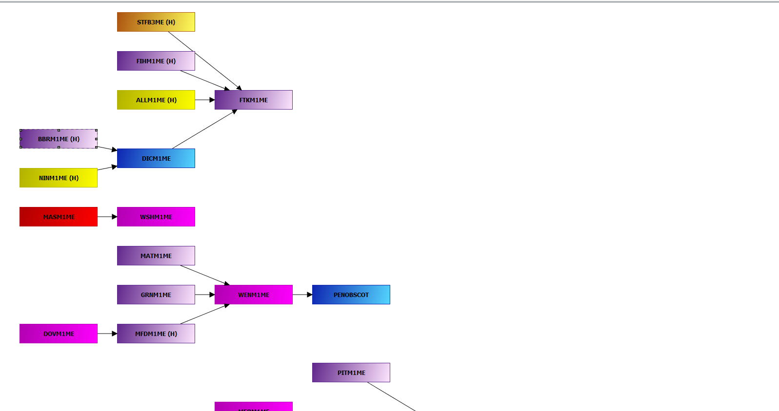
The topology is defined by individual nodes and their connectivity. The topology can be viewed in the topology panel, which shows a block diagram of the topology. An example is shown below.
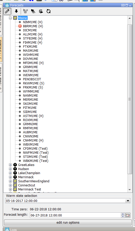
or in the forecast panel, which shows a tree view of the topology.
The behaviour of the forecast panel can also be configured in the topology-file. For example a workflow can be configured for a topology-node. By default the workflow will
run locally when the node is selected in the forecast panel. This can be switched off by setting the option enableAutoRun to false.
The topology.xml plays a central role in configuring an IFD-environment since it is used to configure the forecast panel which is the central panel in an IFD-environment.
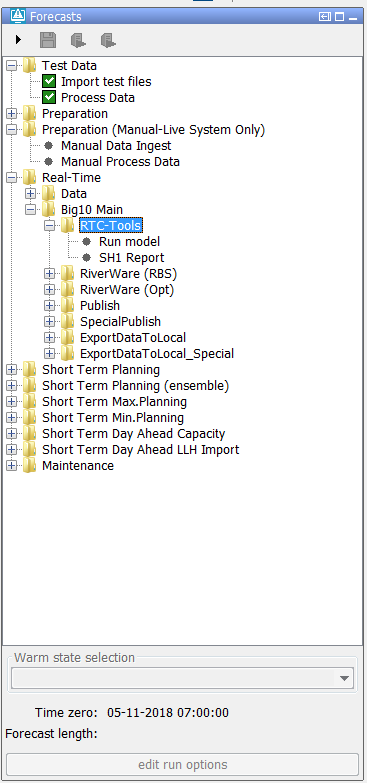
The topology.xml was designed to configure the topology of a FEWS system. There are however also a lot of FEWS-system in which the topology.xml is used to configure the work process of a forecaster.
An example is given below.
Configuration of the nodes in the topology tree
The topology tree can be configured in the following way. The example below shows a simple topology tree with two leaf nodes A and B.
Both of them belong the group node C.
<?xml version="1.0" encoding="UTF-8"?>
<topology xmlns="http://www.wldelft.nl/fews" xmlns:xsi="http://www.w3.org/2001/XMLSchema-instance" xsi:schemaLocation="http://www.wldelft.nl/fews http://fews.wldelft.nl/schemas/version1.0/topology.xsd">
	<nodes id="C" name="C">
		<node id="A" name="A"/>
		<node id="B" name="B"/>
	</nodes>
</topology>
It is possible to run a workflow in IFD mode or in server mode from the topology panel. In the example below some of the node(s) have a workflow configured.
<?xml version="1.0" encoding="UTF-8"?>
<topology xmlns="http://www.wldelft.nl/fews" xmlns:xsi="http://www.w3.org/2001/XMLSchema-instance" xsi:schemaLocation="http://www.wldelft.nl/fews http://fews.wldelft.nl/schemas/version1.0/topology.xsd">
	<nodes id="C" name="C">
		<workflowId>workflowC</workflowId>
		<node id="A" name="A">
			<workflowId>workflowA</workflowId>
		</node>
		<node id="B" name="B"/>
	</nodes>
</topology>
By default all the workflows started from a leaf node are started in IFD mode.
This means that the results of the run are only temporary available in FEWS and that the results are only available visible at the operator client which started the run. As soon as the FEWS system is restarted all the IFD runs will be deleted.
IFD runs are typically used to evaluate the effect of modifiers on the results of a forecast. A workflow which is started from a group node will by default be started as a server run. A server run will run at a FSS when it is started from an operator client. When it is started from a stand alone it will run locally but the results of the run will be available after a restart of the system.
It is possible to change these default settings by using the element localRun.
In the example below the runs from leaf node B will run in server mode and the runs started from the group node C will run in IFD mode.
<?xml version="1.0" encoding="UTF-8"?>
<topology xmlns="http://www.wldelft.nl/fews" xmlns:xsi="http://www.w3.org/2001/XMLSchema-instance" xsi:schemaLocation="http://www.wldelft.nl/fews http://fews.wldelft.nl/schemas/version1.0/topology.xsd">
	<nodes id="C" name="C">
		<workflowId>workflowC</workflowId>
		<localRun>true</localRun>
		<node id="A" name="A">
			<workflowId>workflowA</workflowId>
			<localRun>false</localRun>
		</node>
		<node id="B" name="B"/>
	</nodes>
</topology>
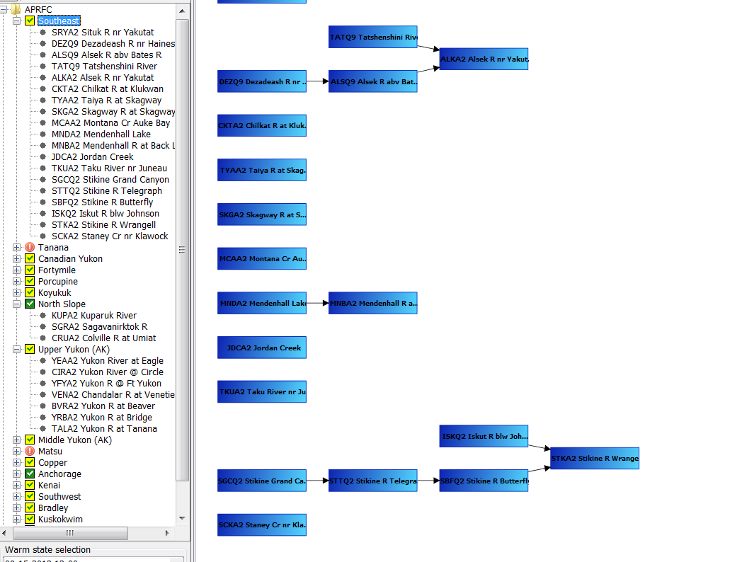
It is possible to connect nodes in the topology. In the example below the node STKA2 is connected to two previous nodes (SBFQ2 and ISKQ2).
<node id="STKA2" name="STKA2 Stikine R Wrangell">
		<previousNodeId>SBFQ2</previousNodeId>
		<previousNodeId>ISKQ2</previousNodeId>
		<workflowId>STKA2_Forecast</workflowId>
</node>
The way nodes are connected plays an important role when running workflows in IFD mode.
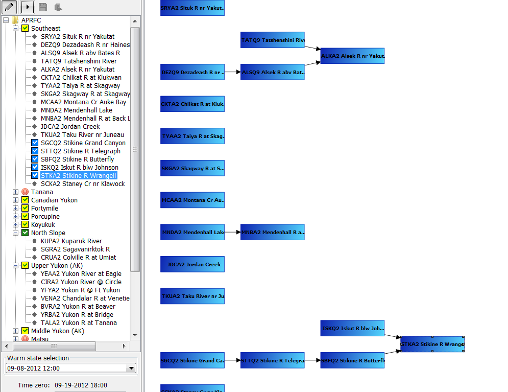
The example below shows the situation before the forecaster starts an IFD run for the node STKA2. The topology tree shows that
this node has not run yet (icon is a black dot) and that it is connected to two previous nodes SBFQ2 and ISKQ2.
When the forecaster starts an IFD run for node STKA2 FEWS will detect that node STKA2 is connected to two other nodes which have to run before the run for STKA2 can be started.
One of these nodes (SBFQ2) also has a previous node which has to run prior to running this node. Before running node STKA2 the IFD system will make sure that first all the necessary previous nodes are run in the correct order before node STKA2 will be run. The example below shows the forecast tree after the run for STKA2 was finished. It shows that not only an IFD run was started for STKA2 but also for all its previous nodes.
Configuration of states, time zero and the forecast length
It is possible to manually select the task properties which will be used in the runs started from the IFD. This can be done in the panel below the forecast tree. The picture belows shows an example of this panel.
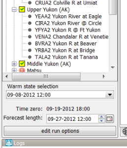
The options which are shown in this panel are configurable. Each node or group of nodes in the topology can have different options.
More advanced options are available in the run options panel. This panel is started when the forecaster clicks on the edit run options button.
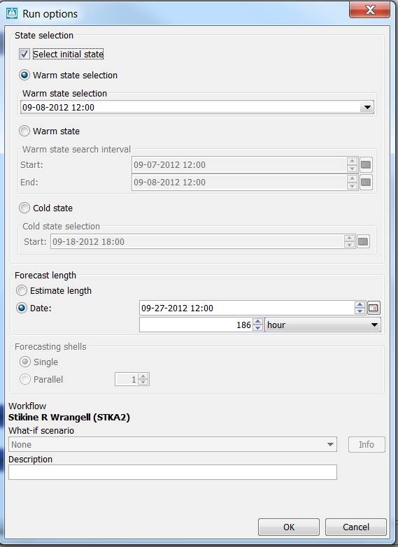
In the section below several typical configuration examples which be explained in detail.
Warm state selection
In a lot of systems, for example NWS systems, only the state selection is configured. The time zero will in this case be equal to the system time.
The forecast length will be determined by the forecast length estimator. After the first run for a node the a time chooser will be shown which will allow the forecaster to edit the forecast length which was determined by the forecast length estimator.
nodes id="APRFC">
		<showModifiers>true</showModifiers>
		<workflowId>APRFC_Forecast</workflowId>
		<warmState unit="day" multiplier="10"/>
		<!-- Topology added for forecast group Southeast -->
		<nodes id="Southeast" name="Southeast">
			<workflowId>Southeast_Forecast</workflowId>
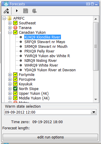
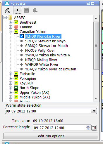
Below a screenshot of the system prior to running a node. The state selection is set to -10 days. The forecast length is not set and the time zero is equal to the system time.
After the run the forecast length which was determined by the forecast length estimator is shown in the panel.
The forecaster can adjust the forecast length by using the time chooser.
It is possible to disable the possiblity to edit the forecast length by using the option useForecastLengthFromInteractiveForecastDisplay.
An configuration example is shown below.
<node id="SRYA2" name="SRYA2 Situk R nr Yakutat">
			<workflowId>SRYA2_Forecast</workflowId>
			<useForecastLengthFromInteractiveForecastDisplay>false</useForecastLengthFromInteractiveForecastDisplay>
</node>
When the system time changes the selected state will also change so the relative time compared to time zero will stay the same.
Relative period panel
When the forecaster wants to run a workflow for a certain period of time then the relative period panel is a good option to use. The picture belows shows an example of the relative period panel.

This option is used, for example, in the HERMES-system. Below a configuration example.
	<node id="ProcessTest" name="Process Data">
		<workflowId>ProcessImports</workflowId>
		<relativePeriod unit="day" start="-30" end="0"/>
		<localRun>false</localRun>
	</node>
When the system time is changed then the start time and end time will also change so that the relative period will stay the same for a topology node.
Cold state from current run
To set the state selection at a node to the cold state selection which was used in another run the option coldStateFromCurrentRun can be used.
Below a configuration example
<node id="rainfallpolicy_tweed" name="Set Rainfall Policy">
			<workflowId>Tweed_Rainfall_Forecast</workflowId>
			<coldStateFromCurrentRun>
				<workflowId>Tweed_URBS_IFD_Forecast</workflowId>
				<coldState unit="day" multiplier="2"/>
			</coldStateFromCurrentRun>
			<defaultModifierId>Rainfall Policy</defaultModifierId>
			<visibleModifierGroup>URBS_Official_Rainfall</visibleModifierGroup>
			<localRun>true</localRun>
			<showRunApprovedForecastButton>false</showRunApprovedForecastButton>
	</node>
In the example above the cold state which was used in the current run from workflow "Tweed URBS IFD forecast" will be used.
It is possible to define a default state selection for the cases that a current run is not available yet. In the example above this default is set to a cold state selection of 2 days before time zero.
If time zero changes the cold state selection should also change to keep the relative period the same.
Forecast length
To set the forecast length at a fixed length the option forecastLength can be used.
It is possible to force the end time of the forecast (time zero plus forecast length) to match a certain time step by using the option initialForecastLengthCardinalTimeStep.
The end time of a node is only forced to the match this time step at the moment the user selects the node for the first time.
To force the end time of a node to match a certain time step in the cases the forecaster tries the edit the default forecast length the option cardinalTimeStepForecastLength can be used.
By default the end time of a node changes when the system time changes so that the forecast length stays the same.
However if for a node the option initialForecastLengthCardinalTimeStep is configured then the end time of the node stays the same if time zero changes.
Below a configuration example of a node for which a forecast length, an initialForecastLengthCardinalTimeStep and a cardinalTimeStepForecastLength is configured.
<node id="B10_Main_RTC" name="Run model">
					<workflowId>Big10_RTCTools_RT</workflowId>
					<forecastLength unit="hour" multiplier="24"/>
					<cardinalTimeStepForecastLength unit="hour"/>
					<initialForecastLengthCardinalTimeStep id="HE6"/>
					<displayGroupId>Main_RT-RTC</displayGroupId>
					<timeSeriesButtonsPanelId>RT_buttons_Main</timeSeriesButtonsPanelId>
					<viewPermission>execute</viewPermission>
					<visibleModifierGroup>RT</visibleModifierGroup>
					<graceTime unit="hour" multiplier="1"/>
					<localRun>true</localRun>
					<saveLocalRunEnabled>true</saveLocalRunEnabled>
					<showRunApprovedForecastButton>true</showRunApprovedForecastButton>
</node>
Below a screenshot of this node after it is selected for the first time.
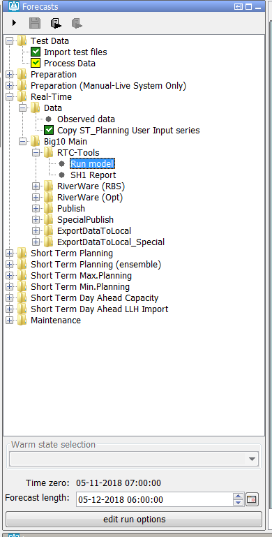
The end time of the run (forecast length) was first set to time zero plus 24 hours. Because this time wasn't a valid time for the configured
initialForecastLengthCardinalTimeStep the end time was set to first valid time prior to the end time.
Below a screenshot of the same node after the sytem time was changed. The time zero is changed but the end time of the node is still fixed at the same time.

Time zero
By default the time zero of a node is equal to the system time and not editable.
It is possible to make the time zero editable and to set it to a fixed date/time.
The code snippet below shows a configuration example.
<node id="ZWF_LHM_Z0_REF2017BP18" name="Files LHM zonder zout">
				<workflowId>ZWF_LHM_Z0_REF2017BP18</workflowId>
				<timeZero date="2004-01-01" time="00:00:00"/>
				<localRun>false</localRun>
</node>
To make the time zero editable and/or to shfit the time zero compared to the system time the option timeZeroShift can be used.
<nodes id="WaterOrder HADT1" name="Water Order Apalachia">
				<timeZeroShift unit="hour" multiplier="0"/>
				<node id="WaterOrder_HADT1" name="Adjust Water Order">
					<locationId>HADT1</locationId>
					<workflowId>CalculateSpill_WaterOrder_HADT1</workflowId>
If the shift is set to 0 then the time zero will be editable but equal to the system time.
Topology groups
It is possible to split the configuration of the topology in separate configuration files.
The main configuration file is always the topology.xml. The other (supporting) configuration files are the topology group files.
An example of a topology group file is shown below.
<?xml version="1.0" encoding="utf-8"?>
<topologyGroup xmlns="http://www.wldelft.nl/fews" xmlns:xsi="http://www.w3.org/2001/XMLSchema-instance" xsi:schemaLocation="http://www.wldelft.nl/fews http://fews.wldelft.nl/schemas/version1.0/topologyGroup.xsd">
	<group id="ForecastGroup_Bear">
		<nodes id="Bear" name="Bear">
			<workflowId>Bear_Forecast</workflowId>
			<node id="MergeMAPBear" name="MergeMAP and Outflow">
				<workflowId>Bear_Forecast</workflowId>
				<moduleInstanceId>SetTimes_Forecast</moduleInstanceId>
				<moduleInstanceId>MergeMAP_Bear_Forecast</moduleInstanceId>
				<moduleInstanceId>Merge_RiverWare_Observed_QT</moduleInstanceId>
				<visibleModifierGroup>None</visibleModifierGroup>
			</node>
		</nodes>
	</group>
</topologyGroup>
The defined topology groups can be used in the topology.xml by using the element groupId. An example is shown below.
<nodes id="InflowForecast" name="Inflow Forecast">
			<warmState unit="day" multiplier="11"/>
			<groupId>ForecastGroup_Bear</groupId>
Interaction with other displays
The forecast panel interacts with the other panels in FEWS in a lot of ways.
It is possible to define which panel or tool window(s) should be made visible after selecting a node.
This can be done using the elements mainPanel and toolWindow.
An example is shown below.
<?xml version="1.0" encoding="utf-8"?>
<topologyGroup xmlns="http://www.wldelft.nl/fews" xmlns:xsi="http://www.w3.org/2001/XMLSchema-instance" xsi:schemaLocation="http://www.wldelft.nl/fews http://fews.wldelft.nl/schemas/version1.0/topologyGroup.xsd">
	<group id="ForecastGroup_Bear">
		<nodes id="Bear" name="Bear">
			<workflowId>Bear_Forecast</workflowId>
			<node id="MergeMAPBear" name="MergeMAP and Outflow">
				<mainPanel>modifiers panel</mainPanel>
				<toolWindow>plot overview</toolWindow>
			</node>
		</nodes>
	</group>
</topologyGroup>
After selecting a node in the topology a plot connected to this node will be automatically displayed in the plot window.
The element displayGroupId can be used to connect a topology node to a display group. After selecting a another topology node FEWS will first try to find a display which has the same location and parameter as currently displayed in the connected display group. If such a display cannot be found the first display of the topology group will be shown.
This behaviour can be disabled by using the element selectFirstPlotOnSelectionChange. If this option is set to true the first plot will always be selected.
The plot overview panel shows an overview of all the displays on the display group.
To be added by Onno...timeSeriesButtonPanelId
To select automatically a zoom extent in the map after selecting a node, the element mapExtentId can be used.
To select a filter automatically after selecting a node the element filterId can be used.
The element forecasterHelperDirectories is a configuration option which applies to all nodes. It can be used to define in which directories the forecaster helper should look for files.
The element enableSelectNodesFromMap is also a configuration option which applies to all nodes. It can be used to configure that the user can select nodes in the topology tree by selecting locations on the map.
If a node is selected on the map a matching topology node with the same location id will be selected.
An area id can be configured for a topology node. This configuration option is used in combination with the archive panel. After selecting a node with an area id configured the area selection in the archive panel will be set to the area id of the selected node.
By default, the ForecasteNotesDisplay shows the notes for the the node (and its parent) that is selected by the user in the Topology GUI. This list of forecast notes can be extended with the notes that are created for the
node with option alwaysVisibleInForecasterNotes=true
Icons
Modifiers
Permissions
Buttons
Configuration options which apply to all nodes
The topology.xml has two types of configuration options. The first group is applied to all nodes, the second group is applied to individual nodes. In this part the first group of options will be explained.
The following global options are available
forecasterHelperDirectories
enableOriginalButtons
enableAutorun
enableAutoSelectParameters
enableRunUpstreamServerNodes
enableRunAllPreviousNodes
enableSelectNodesFromMap
enableAutoSaveOnRun
enableCrossGroupReferencing
selectFirstPlotOnSelectionChange
These global options are configured at the top of the topology.xml before the definition of the nodes.
forecasterHelperDirectories
When present, this element specifies the directories where the forecaster helper should look for the files instead of the INFORMATION_PANEL_FOLDER property in oc_global.properties
enableOriginalButtons
Since 2014.01. By default the toolbar with 2 buttons is used: buttons 'Run' and 'Run approved forecast'. If a group node is selected, both buttons start the workflow of that node. The first button starts the run in IFD-mode, the second button starts the run in server mode. When this element is set to true, the original toolbar with 4 or 5 buttons will be used. The original buttons are: 1) 'Switch to edit/forecast mode' (optional), 2) 'Go to next segment', 3) Re-run segment', 4) 'Re-run forecast group', and 5) 'Run approved forecast'.
enableAutoRun
This option is set to true by default. If a topology node is selected in the forecast panel and a workflow is configured for this node and this option is enabled than the associated workflow will automatically run. By setting this option to false this behaviour can be switched off. Note: This option only works if enableOriginalButtons is set to true.
enableAutoSelectParameters
This option is set to false by default. If a node is selected and a filter is configured for that node than the filter will be selected automatically. If this option is also enabled than the parameters of that filter will also be selected automatically. Because the parameters are also selected after selecting the node the plot display will automatically show the time series of the filters in the plot display.
enableRunUpstreamServerNodes
When this option is set to true upstream server nodes with a workflow are run at the server prior tot running the selected server node.
enableRunAllPreviousNodes
If this option is enabled and the workflow of a node is scheduled to run in IFD mode, all the workflows from the first node in the group to the node which is scheduled to run is started, even if the nodes are not connected in the defined topology. This option is not enabled by default. By default only the options which are connected to the node will be run.
enableSelectNodesFromMap
This option is set to false by default. If this option is enabled it will be possible to select nodes by clicking on the location in the map, if that node has a locationId and a filterId configured in the Topology file.
enableAutoSaveOnRun
Default is false. When this option is set to true all edits will be automatically saved to the database without having to press apply or confirm when a node is run.
enableCrossGroupReferencing
By default the topology only considers nodes which are part of the same group as being linked to the current node.
When FEWS tries to determine what the status of a node is, it will also take into account the nodes which are linked to that node.
If that node is however part of another group then FEWS will ignore that node despite the fact that it is linked to that node.
selectFirstPlotOnSelectionChange
When selecting an other topology node the (thumbnail) plot is selected that shows the same parameter or location as currently displayed. To revert to the behaviour of 2016.01 must set this option to true.