Function: | Configure topology of an IFD environment |
Where to Use? | Mandatory for an IFD installation |
Why to Use? | The topology.xml is necessary to be able to use panels like the topology panel and the forecast panel |
Description: | Topology panel is used to define the topology of an IFD environment. Also the behaviour of the forecast panel which is used to start |
Available since: | DelftFEWS201001 |
Contents
Introduction
The concept of the IFD (interactive forecast displays) was introduced in 2010. A central role in the configuration of the IFD is the topology.xml. This part of the wiki explains the configuration details of the topology.xml.
First the background of the topology.xml wil be explained in the overview section. In the following sections the configuration options will be explained in detail.
Overview
The topology.xml is a mandatory configuration file when you are setting up an IFD-environment. This configuration file is used to configure the topology of a FEWS-system.
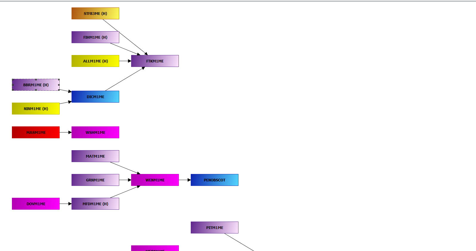
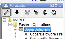
The topology is defined by individual nodes and their connectivity. The topology can be viewed in the topology panel, which shows a block diagram of the topology. An example is shown below.
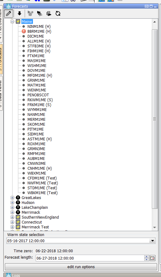
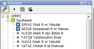
or in the forecast panel, which shows a tree view of the topology.
The behaviour of the forecast panel can also be configured in the topology-file. This will be explained in more detail in the next sections.
The topology.xml plays a central role in configuring an IFD-environment since it is used to configure the forecast panel which is the central panel in an IFD-environment.
The topology.xml was originally designed to configure the topology of a FEWS system but there are a lot of FEWS systems in which the topolog.xml is used to configure the work process of the forecaster.
An example is given below.
Running workflows from the topology tree
The topology tree can be configured in the following way. The example below shows a simple topology tree with two leaf nodes A and B.
Both of them belong the group node C.
<?xml version="1.0" encoding="UTF-8"?>
<topology xmlns="http://www.wldelft.nl/fews" xmlns:xsi="http://www.w3.org/2001/XMLSchema-instance" xsi:schemaLocation="http://www.wldelft.nl/fews http://fews.wldelft.nl/schemas/version1.0/topology.xsd">
	<nodes id="C" name="C">
		<node id="A" name="A"/>
		<node id="B" name="B"/>
	</nodes>
</topology>
It is possible to run workflows from the topology panel. In the example below some of the node(s) have a workflow configured.
<?xml version="1.0" encoding="UTF-8"?>
<topology xmlns="http://www.wldelft.nl/fews" xmlns:xsi="http://www.w3.org/2001/XMLSchema-instance" xsi:schemaLocation="http://www.wldelft.nl/fews http://fews.wldelft.nl/schemas/version1.0/topology.xsd">
	<nodes id="C" name="C">
		<workflowId>workflowC</workflowId>
		<node id="A" name="A">
			<workflowId>workflowA</workflowId>
		</node>
		<node id="B" name="B"/>
	</nodes>
</topology>
IFD runs
By default all the workflows started from a leaf node are started in IFD mode. The results of an IFD-run are only temporary available in FEWS (until the next restart) and are only available visible at the operator client which started the run.
IFD runs are typically used to evaluate the effect of modifiers on the results of a forecast.
Server run
A workflow which is started from a group node will by default be started as a server run. A server run will run at a FSS when it is started from an operator client. When it is started from a stand alone it will run locally but the results of the run will be available after a restart of the system.
It is possible to change these default settings by using the element localRun.
In the example below the runs from leaf node B will run in server mode and the runs started from the group node C will run in IFD mode.
<?xml version="1.0" encoding="UTF-8"?>
<topology xmlns="http://www.wldelft.nl/fews" xmlns:xsi="http://www.w3.org/2001/XMLSchema-instance" xsi:schemaLocation="http://www.wldelft.nl/fews http://fews.wldelft.nl/schemas/version1.0/topology.xsd">
	<nodes id="C" name="C">
		<workflowId>workflowC</workflowId>
		<localRun>true</localRun>
		<node id="A" name="A">
			<workflowId>workflowA</workflowId>
			<localRun>false</localRun>
		</node>
		<node id="B" name="B"/>
	</nodes>
</topology>
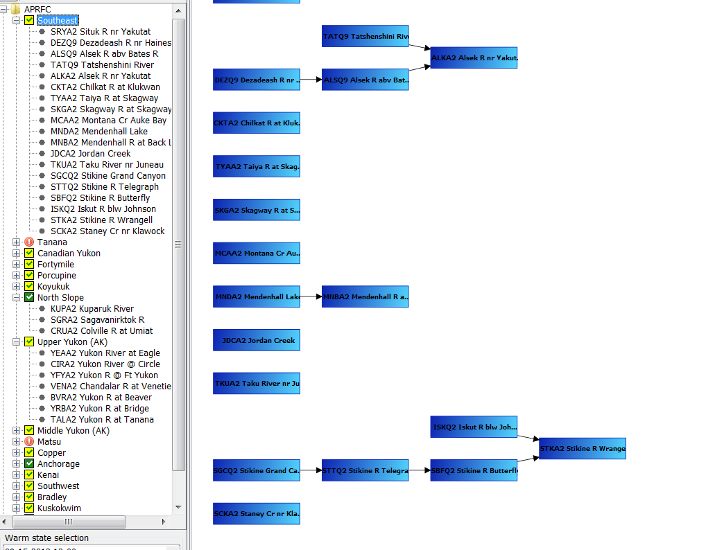
It is possible to connect nodes in the topology. In the example below the node STKA2 is connected to two previous nodes (SBFQ2 and ISKQ2).
<node id="STKA2" name="STKA2 Stikine R Wrangell">
		<previousNodeId>SBFQ2</previousNodeId>
		<previousNodeId>ISKQ2</previousNodeId>
		<workflowId>STKA2_Forecast</workflowId>
</node>
The way nodes are connected plays an important role when running workflows in IFD mode.
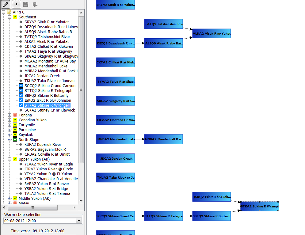
The example below shows the situation before the forecaster starts an IFD run for the node STKA2. The topology tree shows that
this node has not run yet (icon is a black dot) and that it is connected to two previous nodes SBFQ2 and ISKQ2.
When the forecaster starts an IFD run for node STKA2 FEWS will detect that node STKA2 is connected to two other nodes which have to run before the run for STKA2 can be started.
One of these nodes (SBFQ2) also has a previous node which has to run prior to running this node. Before running node STKA2 the IFD system will make sure that first all the necessary previous nodes are run in the correct order before node STKA2 will be run. The example below shows the forecast tree after the run for STKA2 was finished. It shows that not only an IFD run was started for STKA2 but also for all its previous nodes.
By default the workflow on a leaf node is started automatically after selecting the node. This can be disabled by setting the option enableAutoRun to false.
The option will apply to all nodes.
For IFD runs the connected previous nodes are always started before the IFD run for the selected node can be run.
For server runs the connected previous nodes are by default not taken into account. If the option enableRunUpstreamServerNodes is set to true the previous nodes will also be started prior to running the workflow of the selected node.
The option checkStatusPreviousServerRun can be used to force that a server run can only be started if the status of all of its previous nodes is fully succesfull.
Previous nodes which are conntected to a node but belong to a different group in the topology tree are ignored by default when starting previous nodes for a selected node. By setting the option enableCrossGroupNodeReferencing to true previous nodes in a different group will also be taken into account.
Run options panel
It is possible to manually select the task properties which will be used in the runs started from the IFD. This can be done in the panel below the forecast tree. The picture belows shows an example of this panel.
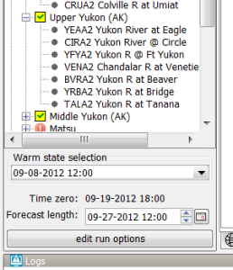
The options which are shown in this panel are configurable. Each node or group of nodes in the topology can have different options.
More advanced options are available in the run options panel. This panel is started when the forecaster clicks on the edit run options button.
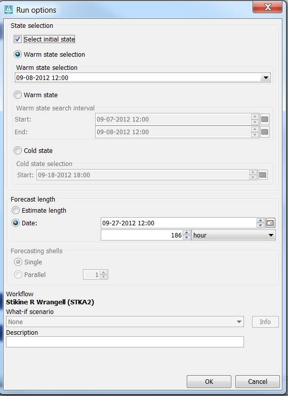
The "edit run options" button can be disabled by setting the option disabledAdvancedButton to false. The "edit run options" button can be disabled for a single node or group of nodes and its children.
In the section below several typical configuration examples which be explained in detail.
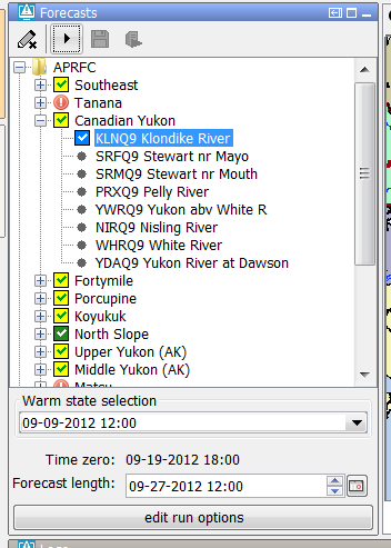
Warm state selection
In a lot of systems, for example NWS systems, only the state selection is configured. The time zero will in this case be equal to the system time.
The forecast length will be determined by the forecast length estimator. After the first run for a node the a time chooser will be shown which will allow the forecaster to edit the forecast length which was determined by the forecast length estimator.
nodes id="APRFC">
		<showModifiers>true</showModifiers>
		<workflowId>APRFC_Forecast</workflowId>
		<warmState unit="day" multiplier="10"/>
		<!-- Topology added for forecast group Southeast -->
		<nodes id="Southeast" name="Southeast">
			<workflowId>Southeast_Forecast</workflowId>
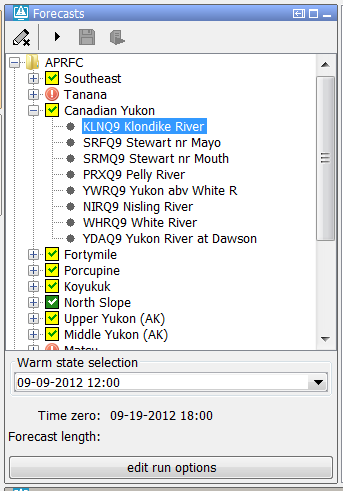
Below a screenshot of the system prior to running a node. The state selection is set to -10 days. The forecast length is not set and the time zero is equal to the system time.
After the run the forecast length which was determined by the forecast length estimator is shown in the panel.
The forecaster can adjust the forecast length by using the time chooser.
It is possible to disable the possiblity to edit the forecast length by using the option useForecastLengthFromInteractiveForecastDisplay.
An configuration example is shown below.
<node id="SRYA2" name="SRYA2 Situk R nr Yakutat">
			<workflowId>SRYA2_Forecast</workflowId>
			<useForecastLengthFromInteractiveForecastDisplay>false</useForecastLengthFromInteractiveForecastDisplay>
</node>
When the system time changes the selected state will also change so the relative time compared to time zero will stay the same.
warm state selection period
The option warm state selection period can be used to set the state selection to a period in which the system will search for a warm state.
An example of a node which is configured with a warm state search period is given below.
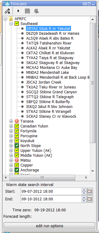
A configuration example is given below.
		<nodes id="Southeast" name="Southeast">
			<workflowId>Southeast_Forecast</workflowId>
			<warmStateSelectionPeriod unit="day" start="-12" end="-9"/>
			<node id="SRYA2" name="SRYA2 Situk R nr Yakutat">
				<workflowId>SRYA2_Forecast</workflowId>
				<useForecastLengthFromInteractiveForecastDisplay>false</useForecastLengthFromInteractiveForecastDisplay>
			</node>
Cold state selection
It is also possible to set the default state selection for a node or a group of nodes to a cold state selection. This is used, for example, in FEWS system which are used for calibration purposes.
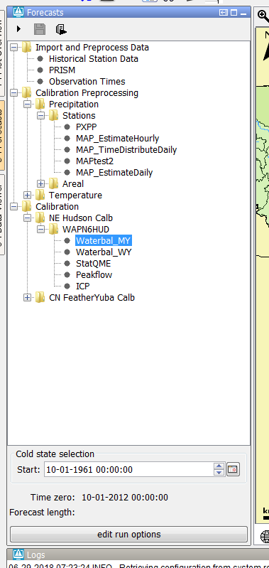
An configuration example is given below.
	<nodes id="WAPN6HUD_calb" name="WAPN6HUD">
				<workflowId>WAPN6HUD_Stats_Calibration</workflowId>
				<coldState unit="day" multiplier="18628"/>
				<node id="WAPN6HUD_Waterbalance_Multi-year" name="Waterbal_MY">
no initial state
The option noInitialState can be used to disable the state selection for a node so that the state will be selected by the workflow.
An example of a node which has this option enabled is shown below.
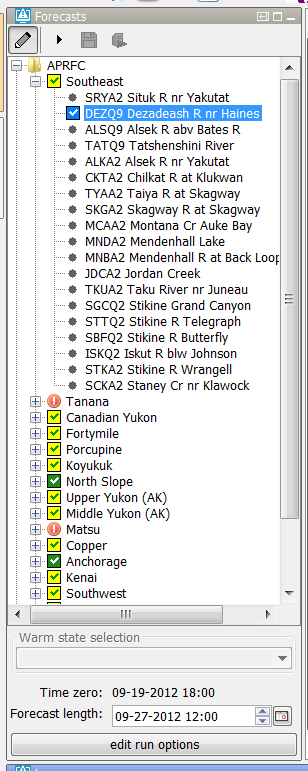
A configuration example is given below.
	<nodes id="Southeast" name="Southeast">
			<workflowId>Southeast_Forecast</workflowId>
			<noInitialState></noInitialState>
Relative period panel
When the forecaster wants to run a workflow for a certain period of time then the relative period panel is a good option to use. The picture belows shows an example of the relative period panel.

This option is used, for example, in the HERMES-system. Below a configuration example.
	<node id="ProcessTest" name="Process Data">
		<workflowId>ProcessImports</workflowId>
		<relativePeriod unit="day" start="-30" end="0"/>
		<localRun>false</localRun>
	</node>
When the system time is changed then the start time and end time will also change so that the relative period will stay the same for a topology node.
Cold state from current run
To set the state selection at a node to the cold state selection which was used in another run the option coldStateFromCurrentRun can be used.
Below a configuration example
<node id="rainfallpolicy_tweed" name="Set Rainfall Policy">
			<workflowId>Tweed_Rainfall_Forecast</workflowId>
			<coldStateFromCurrentRun>
				<workflowId>Tweed_URBS_IFD_Forecast</workflowId>
				<coldState unit="day" multiplier="2"/>
			</coldStateFromCurrentRun>
			<defaultModifierId>Rainfall Policy</defaultModifierId>
			<visibleModifierGroup>URBS_Official_Rainfall</visibleModifierGroup>
			<localRun>true</localRun>
			<showRunApprovedForecastButton>false</showRunApprovedForecastButton>
	</node>
In the example above the cold state which was used in the current run from workflow "Tweed URBS IFD forecast" will be used.
It is possible to define a default state selection for the cases that a current run is not available yet. In the example above this default is set to a cold state selection of 2 days before time zero.
If time zero changes the cold state selection should also change to keep the relative period the same.
Relative period panel with only a start time
Forecast length
To set the forecast length at a fixed length the option forecastLength can be used.
It is possible to force the end time of the forecast (time zero plus forecast length) to match a certain time step by using the option initialForecastLengthCardinalTimeStep.
The end time of a node is only forced to the match this time step at the moment the user selects the node for the first time.
To force the end time of a node to match a certain time step in the cases the forecaster tries the edit the default forecast length the option cardinalTimeStepForecastLength can be used.
By default the end time of a node changes when the system time changes so that the forecast length stays the same.
However if for a node the option initialForecastLengthCardinalTimeStep is configured then the end time of the node stays the same if the time zero changes.
Below a configuration example of a node for which a forecast length, an initialForecastLengthCardinalTimeStep and a cardinalTimeStepForecastLength is configured.
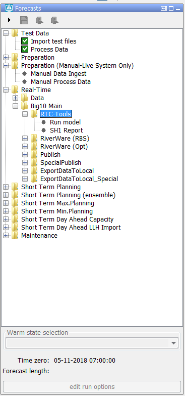
<node id="B10_Main_RTC" name="Run model">
					<workflowId>Big10_RTCTools_RT</workflowId>
					<forecastLength unit="hour" multiplier="24"/>
					<cardinalTimeStepForecastLength unit="hour"/>
					<initialForecastLengthCardinalTimeStep id="HE6"/>
					<displayGroupId>Main_RT-RTC</displayGroupId>
					<timeSeriesButtonsPanelId>RT_buttons_Main</timeSeriesButtonsPanelId>
					<viewPermission>execute</viewPermission>
					<visibleModifierGroup>RT</visibleModifierGroup>
					<graceTime unit="hour" multiplier="1"/>
					<localRun>true</localRun>
					<saveLocalRunEnabled>true</saveLocalRunEnabled>
					<showRunApprovedForecastButton>true</showRunApprovedForecastButton>
</node>
Below a screenshot of this node after it is selected for the first time.
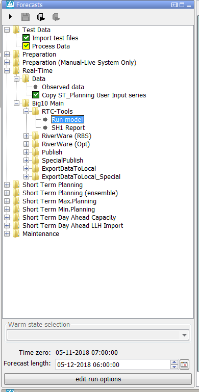
The end time of the run (forecast length) was first set to time zero plus 24 hours. Because this time wasn't a valid time for the configured
initialForecastLengthCardinalTimeStep the end time was set to first valid time prior to the end time.
Below a screenshot of the same node after the sytem time was changed. The time zero is changed but the end time of the node is still fixed at the same time.

Time zero
By default the time zero of a node is equal to the system time and not editable.
It is possible to make the time zero editable and to set it to a fixed date/time.
The code snippet below shows a configuration example.
<node id="ZWF_LHM_Z0_REF2017BP18" name="Files LHM zonder zout">
				<workflowId>ZWF_LHM_Z0_REF2017BP18</workflowId>
				<timeZero date="2004-01-01" time="00:00:00"/>
				<localRun>false</localRun>
</node>
To make the time zero editable and/or to shfit the time zero compared to the system time the option timeZeroShift can be used.
<nodes id="WaterOrder HADT1" name="Water Order Apalachia">
				<timeZeroShift unit="hour" multiplier="0"/>
				<node id="WaterOrder_HADT1" name="Adjust Water Order">
					<locationId>HADT1</locationId>
					<workflowId>CalculateSpill_WaterOrder_HADT1</workflowId>
If the shift is set to 0 then the time zero will be editable but equal to the system time.
Topology groups
It is possible to split the configuration of the topology in separate configuration files.
The main configuration file is always the topology.xml. The other (supporting) configuration files are the topology group files.
An example of a topology group file is shown below.
<?xml version="1.0" encoding="utf-8"?>
<topologyGroup xmlns="http://www.wldelft.nl/fews" xmlns:xsi="http://www.w3.org/2001/XMLSchema-instance" xsi:schemaLocation="http://www.wldelft.nl/fews http://fews.wldelft.nl/schemas/version1.0/topologyGroup.xsd">
	<group id="ForecastGroup_Bear">
		<nodes id="Bear" name="Bear">
			<workflowId>Bear_Forecast</workflowId>
			<node id="MergeMAPBear" name="MergeMAP and Outflow">
				<workflowId>Bear_Forecast</workflowId>
				<moduleInstanceId>SetTimes_Forecast</moduleInstanceId>
				<moduleInstanceId>MergeMAP_Bear_Forecast</moduleInstanceId>
				<moduleInstanceId>Merge_RiverWare_Observed_QT</moduleInstanceId>
				<visibleModifierGroup>None</visibleModifierGroup>
			</node>
		</nodes>
	</group>
</topologyGroup>
The defined topology groups can be used in the topology.xml by using the element groupId. An example is shown below.
<nodes id="InflowForecast" name="Inflow Forecast">
			<warmState unit="day" multiplier="11"/>
			<groupId>ForecastGroup_Bear</groupId>
Interaction with other displays
The forecast panel interacts with the other panels in FEWS in a lot of ways.
It is possible to define which panel or tool window(s) should be made visible after selecting a node.
This can be done using the elements mainPanel and toolWindow.
An example is shown below.
<?xml version="1.0" encoding="utf-8"?>
<topologyGroup xmlns="http://www.wldelft.nl/fews" xmlns:xsi="http://www.w3.org/2001/XMLSchema-instance" xsi:schemaLocation="http://www.wldelft.nl/fews http://fews.wldelft.nl/schemas/version1.0/topologyGroup.xsd">
	<group id="ForecastGroup_Bear">
		<nodes id="Bear" name="Bear">
			<workflowId>Bear_Forecast</workflowId>
			<node id="MergeMAPBear" name="MergeMAP and Outflow">
				<mainPanel>modifiers panel</mainPanel>
				<toolWindow>plot overview</toolWindow>
			</node>
		</nodes>
	</group>
</topologyGroup>
After selecting a node in the topology a plot connected to this node will be automatically displayed in the plot window.
The element displayGroupId can be used to connect a topology node to a display group. After selecting a another topology node FEWS will first try to find a display which has the same location and parameter as currently displayed in the connected display group. If such a display cannot be found the first display of the topology group will be shown.
This behaviour can be disabled by using the element selectFirstPlotOnSelectionChange. If this option is set to true the first plot will always be selected.
The plot overview panel shows an overview of all the displays on the display group.
To be added by Onno...timeSeriesButtonPanelId
To select automatically a zoom extent in the map after selecting a node, the element mapExtentId can be used.
To select a filter automatically after selecting a node the element filterId can be used. By default the parameters in the filters will not be selected automatically.
To enable that the parameters will also be selected automatically the option enableAutoSelectParameters should be set to true.
The element forecasterHelperDirectories is a configuration option which applies to all nodes. It can be used to define in which directories the forecaster helper should look for files.
The element enableSelectNodesFromMap is also a configuration option which applies to all nodes. It can be used to configure that the user can select nodes in the topology tree by selecting locations on the map.
If a node is selected on the map a matching topology node with the same location id will be selected.
An area id can be configured for a topology node. This configuration option is used in combination with the archive panel. After selecting a node with an area id configured the area selection in the archive panel will be set to the area id of the selected node.
By default, the ForecasteNotesDisplay shows the notes for the the node (and its parent) that is selected by the user in the Topology GUI. This list of forecast notes can be extended with the notes that are created for the
node with option alwaysVisibleInForecasterNotes=true
Icons
Grace time
The icons in the topology tree can be used to view the status of node. The icon show if a workflow has run for that node and what status of that run is.
A green or blue icon indicate that the workflow was succesfull, The icons also indicate if the time zero which was used in the last run of a node is the same as the time zero which is currently selected for a node.
If the time zero is different then the icon will indicate that the available run is invalid. In systems which have a small cardinal time step this behaviour can be problematic because runs are marked as being invalid too quickly.
The element graceTime can be used to introduce a grace time for the time zero was used in a run. If the difference between the time zero for a node and the time zero which was used in the last run is less then the grace time then the run will still be marked as valid.
useStatusParentNode
If the status of a topology node is determined by a server run and its parent node has a more recent server run then the node will inherit the status from its parent.
Modifiers
showModifiers
The option is only available at group nodes. By default the modifiers panel doesn't show modifiers at group nodes. This choice was made because of performance reasons.
In addition it is not common that modifiers are made at group nodes. In the cases that it is required that modifiers can be shown (and editted) at a group node the default behaviour can be
changed. This option is only available at group nodes.
hideModifiersOverviewPanel
The modifiers panel consists of two parts. An overview panel which shows all the modifiers which are available for the selected node and a detail panel which shows the details of the modifier which is selected in the overview panel or the new modifier which the user is creating.
The overview panel uses the half of the space of the modifers panel. By hiding this panel a lot of space is available for the detail panel. This is a usefull feature when users only create modifiers at a node and want to use all the available space for the detail panel.
modifiersReadOnly
This option can be used to disable the possiblity to add, edit or delete modifiers at a node.
defaultModifierId
If a default modifier id is defined at a node then the first available modifier of the defined type will be selected in the modifiers panel. If there is no modifier of this type is available then a new modifier template is created in the modifiers detail panel. An example is shown below.
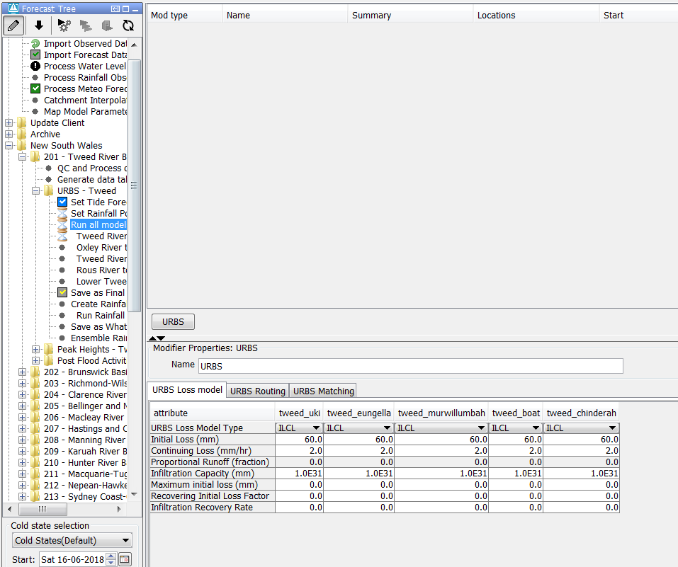
In the example above a node "Run all Models" is shown. This node has a defaultModifierId defined and set to URBS.
After selecting the node "Run all models" a modifiers template for the modifiers type "URBS" will be created. The user can edit this template and create a new modifier by pressing apply.
Below an another example
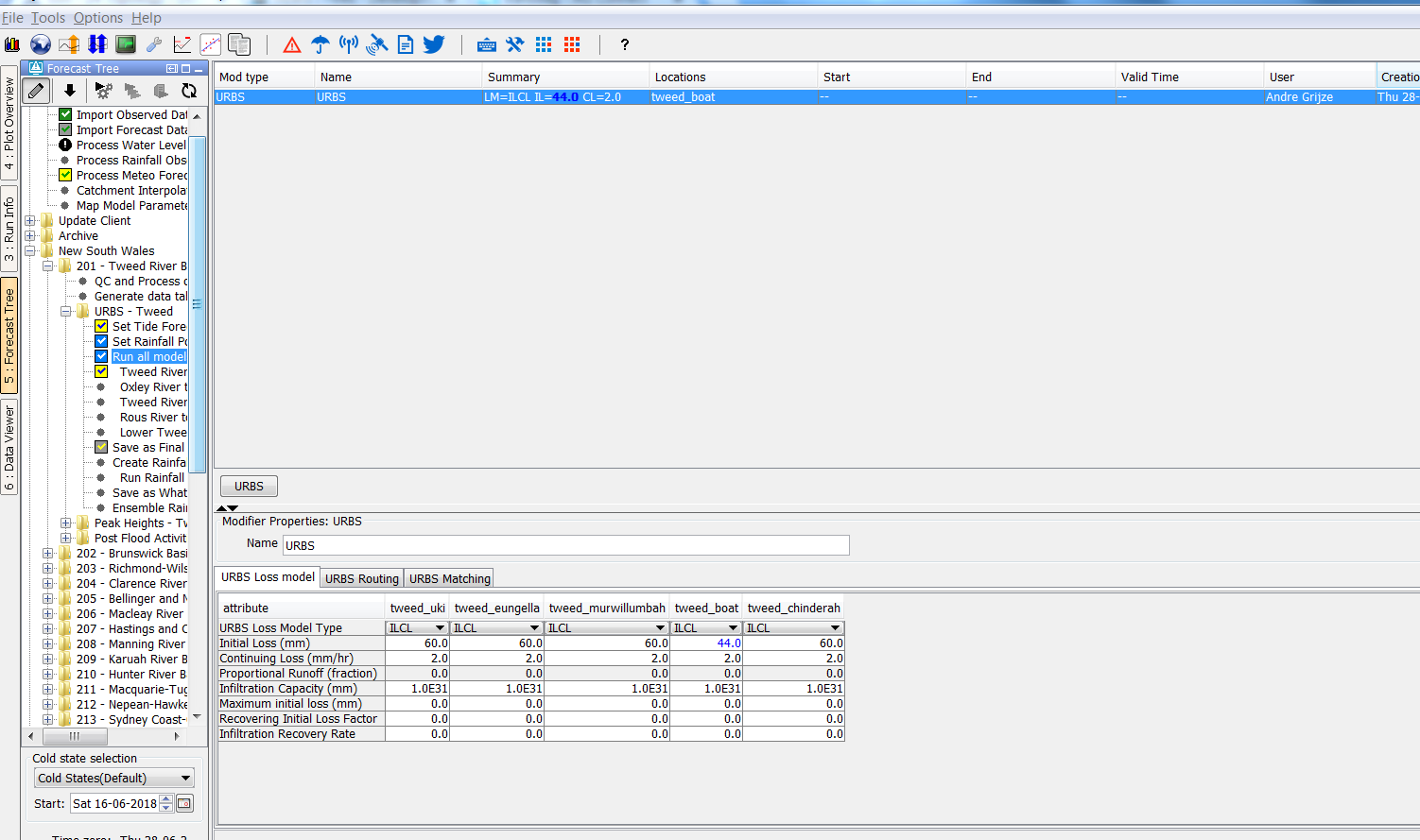
In this example the user has selected the same node. The difference with the previous example is that there is already a modifier of type URBS available.
Because this modifier is available it will be selected instead of creating a new modifiers template.
onlyAllowEditDefaultModifier
If this option is selected only the defined modifier default modifier is selected.
visibleModifierGroup
This option defines the group of modifiers which is visible and edittable at a node. It is possible to define multiple visible modifier groups for a node. By default all modifiers are visible and edittable.
The modifier group should be defined in the modifierTypes.xml.
Permissions
There are several configurations options available with regard to permissions.
viewPermission
This permission controls who can view this node
runWorkflowLocallyPermission
Permission to run the workflow for a node locally
runWorkflowAtServerPermission
Permission to run the workflow for a node at the server
runSecondaryWorkflowPermission
Since 201801. Permission to run the secondary workflow
Buttons
At the top of the forecast panel a group of buttons is shown.
The first FEWS applications which used the forecast panel had a button panel which had 6 buttons.
An example is given below.
The reduce the number of buttons which were shown in this panel a new design for this button panel was made.
This design offered the same functionality but had less buttons.
An example is given below.
By default the button panel which is showed above is available.
To switch to the button panel with more buttons the element enableOriginalButtons can be used.
An config example is shown below.
<?xml version="1.0" encoding="UTF-8"?>
<!-- edited with XMLSpy v2014 rel. 2 sp1 (http://www.altova.com) by Afdeling ICT (Stichting Deltares) -->
<topology xmlns="http://www.wldelft.nl/fews" xmlns:xsi="http://www.w3.org/2001/XMLSchema-instance" xsi:schemaLocation="http://www.wldelft.nl/fews http://fews.wldelft.nl/schemas/version1.0/topology.xsd">
	<enableOriginalButtons>true</enableOriginalButtons>
	<enableAutoRun>false</enableAutoRun>
	<nodes id="NWM" name="Nationaal Water Model">
		<nodes id="Zoetwater" name="Zoetwater">
			<groupId>GroupZoetwater</groupId>
		</nodes>
		<nodes id="Zoetwater_files" name="Prepare Zoetwater files">
			<groupId>GroupZoetwater_Files</groupId>
		</nodes>
	</nodes>
</topology>
The element saveLocalRunEnabled can be used to allow the user to promote a local IFD run to a permanent server run.
If this element is set to true for the selected node and an IFD run is available for the selected node the save-button in the button bar will be enabled.
The element showRunApprovedForecastButton can be used to enable the user to start server runs from nodes for which the option localRun is set to true.
This means that users can start IFD-runs from that node but also server runs.
The element showMacroButton can be used to enable a button in the Run options dialog which allows the user to start a run with pre-defined task properties.